Latency is a time interval between the stimulation and response, or, from a more general point of view, as a time delay between the cause and the effect of some physical change in the system being observed. Latency is physically a consequence of the limited velocity with which any physical interaction can propagate. This velocity is always lower than or equal to the speed of light. Therefore, every physical system that has spatial dimensions different from zero will experience some sort of latency, regardless of the nature of stimulation that it has been exposed to.
The precise definition of latency depends on the system being observed and the nature of stimulation. In communications, the lower limit of latency is determined by the medium being used for communications. In reliable two-way communication systems, latency limits the maximum rate that information can be transmitted, as there is often a limit on the amount of information that is "in-flight" at any one moment. In the field of human–machine interaction, perceptible latency has a strong effect on user satisfaction and usability.
Communication latency
Packet-switched networks
See also: Lag and Bandwidth-delay product
Network latency in a packet-switched network is measured either one-way (the time from the source sending a packet to the destination receiving it), or round-trip delay time (the one-way latency from source to destination plus the one-way latency from the destination back to the source). Round-trip latency is more often quoted, because it can be measured from a single point. Note that round trip latency excludes the amount of time that a destination system spends processing the packet. Many software platforms provide a service called ping that can be used to measure round-trip latency. Ping performs no packet processing; it merely sends a response back when it receives a packet (i.e. performs a no-op), thus it is a first rough way of measuring latency. Ping cannot perform accurate measurements, principally because it uses the ICMP protocol that is used only for diagnostic or control purposes, and differs from real communication protocols such as TCP. Furthermore, routers and ISP's might apply different traffic shaping policies to different protocols.
For more accurate measurements it is better to use specific software (for example: lft, paketto, hping, superping.d, NetPerf, IPerf)
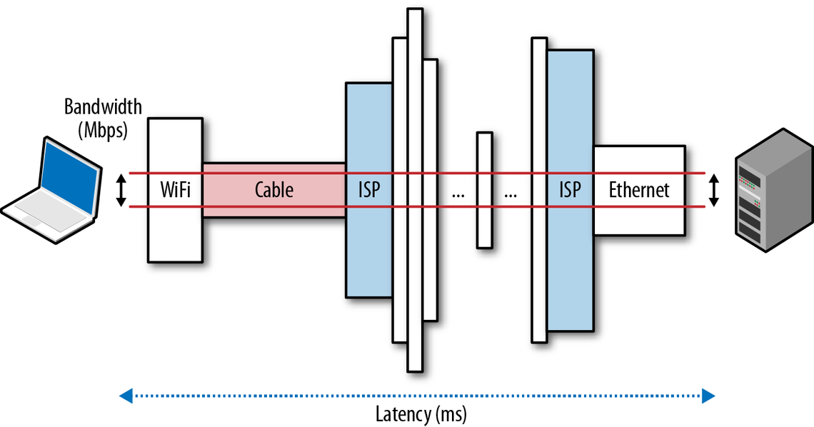
However, in a non-trivial network, a typical packet will be forwarded over many links via many gateways, each of which will not begin to forward the packet until it has been completely received. In such a network, the minimal latency is the sum of the minimum latency of each link, plus the transmission delay of each link except the final one, plus the forwarding latency of each gateway. In practice, this minimal latency is further augmented by queuing and processing delays. Queuing delay occurs when a gateway receives multiple packets from different sources heading towards the same destination. Since typically only one packet can be transmitted at a time, some of the packets must queue for transmission, incurring additional delay. Processing delays are incurred while a gateway determines what to do with a newly received packet. A new and emergent behavior called bufferbloat can also cause increased latency that is an order of magnitude or more. The combination of propagation, serialization, queuing, and processing delays often produces a complex and variable network latency profile.
Latency limits total throughput in reliable two-way communication systems as described by the bandwidth-delay product.
Fiber optics
Latency is largely a function of the speed of light, which is 299,792,458 meters/second in vacuum. This would equate to a latency of 3.33 µs for every kilometer of path length. The index of refraction of most fibre optic cables is about 1.5, meaning that light travels about 1.5 times as fast in a vacuum as it does in the cable. This works out to about 4.9 µs of latency for every kilometer. In shorter metro networks, the latency performance rises a bit more due to building risers and cross-connects and can bring the latency as high as 5 µs per kilometer.
It follows that to calculate latency of a connection, one has to know the distance traveled by the fibre, which is rarely a straight line, since it has to traverse geographic contours and obstacles, such as roads and railway tracks, as well as other rights-of-way. Due to imperfections in the fibre, light degrades as it is transmitted through it. For distances of greater than 100 kilometers, either amplifiers or regenerators need to be deployed. Passive amplifiers typically add less latency than regenerators, at the cost of compounding attenuation, though in both cases it can be highly variable, and so needs to be taken into account. In particular, legacy spans are more likely to make use of higher latency regenerators.
Satellite transmission
This is illustrated when a news presenter in a studio talks with a reporter in a distant place. The signal travels from the newsreader via communication satellite situated in geosynchronous orbit to the reporter and then goes all the way back to geosynchronous orbit and then to the studio, resulting in a journey of over one hundred thousand kilometers . This full hop time lag is easily noticeable. Even though the signal travels at the speed of light, it still requires about half a second to travel that distance (not including the much smaller latencies inside the communications equipment).
Low-Earth orbit is sometimes used to cut this delay, at the expense of more complicated satellite tracking on the ground and requiring more satellites in the satellite constellation to ensure continuous coverage.
Audio latency
Main article: Latency (audio)
Audio latency is the delay between when an audio signal enters and when it emerges from a system. Potential contributors to latency in an audio system include analog-to-digital conversion, buffering, digital signal processing, transmission time, digital-to-analog conversion and the speed of sound in air.
Operational latency
Any individual workflow within a system of workflows can be subject to some type of operational latency. It may even be the case that an individual system may have more than one type of latency, depending on the type of participant or goal-seeking behavior. This is best illustrated by the following two examples involving air travel.
Consumer view
From the point of view of a passenger, latency can be described as follows. Suppose John Doe flies from London to New York. The latency of his trip is the time it takes him to go from his house in England to the hotel he is staying at in New York. This is independent of the throughput of the London-New York air link – whether there were 100 passengers a day making the trip or 10000, the latency of the trip would remain the same.
Producer view
From the point of view of flight operations personnel, latency can be entirely different. Consider the staff at the London and New York airports. Only a limited number of planes are able to make the transatlantic journey, so when one lands they must prepare it for the return trip as quickly as possible. It might take, for example:
- 35 minutes to clean a plane
- 15 minutes to refuel a plane
- 10 minutes to load the passengers
- 30 minutes to load the cargo
Assuming the above are done one after another, minimum plane turnaround time is:
35+15+10+30 = 90
However, cleaning, refueling and loading the cargo can be done at the same time. Passengers can be loaded after cleaning is complete. The reduced latency, then, is:
35 + 10 = 451530Minimum latency = 45
The people involved in the turnaround are interested only in the time it takes for their individual tasks. When all of the tasks are done at the same time, however, it is possible to reduce the latency to the length of the longest task. If some steps have prerequisites, it becomes more difficult to perform all steps in parallel. In the example above, the requirement to clean the plane before loading passengers results in a minimum latency longer than any single task.
Mechanical latency
Any mechanical process encounters limitations modeled by Newtonian physics. The behavior of disk drives provides an example of mechanical latency. Here, it is the time needed for the data encoded on a platter to rotate from its current position to a position adjacent to the read-write head as well as the seek time required for the actuator arm for the read-write head to be positioned above the appropriate track. This is also known as rotational latency and seek time since the basic term latency is also applied to the time required by a computer's electronics and software to perform polling, interrupts, and direct memory access.
Computer hardware and operating system latency
Further information: Access time
Computers run sets of instructions called a process. In operating systems, the execution of the process can be postponed if other processes are also executing. In addition, the operating system can schedule when to perform the action that the process is commanding. For example, suppose a process commands that a computer card's voltage output be set high-low-high-low and so on at a rate of 1000 Hz. The operating system may choose to adjust the scheduling of each transition (high-low or low-high) based on an internal clock. The latency is the delay between the process instruction commanding the transition and the hardware actually transitioning the voltage from high to low or low to high.
On Microsoft Windows, it appears that the timing of commands to hardware is not exact. Empirical data suggest that Windows (using the Windows sleep timer which accepts millisecond sleep times) will schedule on a 1024 Hz clock and will delay 24 of 1024 transitions per second to make an average of 1000 Hz for the update rate. This can have serious ramifications for discrete-time algorithms that rely on fairly consistent timing between updates such as those found in control theory. The sleep function or similar windows API were at no point designed for accurate timing purposes. Certain multimedia-oriented API routines like timeGetTime() and its siblings provide better timing consistency. However, consumer- and server-grade Windows (as of 2011 those based on NT kernel) were not to be real-time operating systems. Drastically more accurate timings could be achieved by using dedicated hardware extensions and control-loop cards.
Linux may have the same problems with scheduling of hardware I/O. The problem in Linux is mitigated by support for posix real-time extensions, and the possibility of using a kernel with the PREEMPT_RT patch applied.
On embedded systems, the real-time execution of instructions is often supported by the low-level embedded operating system.
In simulators and simulation
In simulation applications, 'latency' refers to the time delay, normally measured in milliseconds (1/1,000 sec), between initial input and an output clearly discernible to the simulator trainee or simulator subject. Latency is sometimes also called transport delay.
- Some authorities distinguish between latency and transport delay by using the term 'latency' in the sense of the extra time delay of a system over and above the reaction time of the vehicle being simulated, but this requires a detailed knowledge of the vehicle dynamics and can be controversial.
- Importance of Motion and Visual Latencies. In simulators with both visual and motion systems, it is particularly important that the latency of the motion system not be greater than of the visual system, or symptoms of simulator sickness may result. This is because in the real world, motion cues are those of acceleration and are quickly transmitted to the brain, typically in less than 50 milliseconds; this is followed some milliseconds later by a perception of change in the visual scene. The visual scene change is essentially one of change of perspective and/or displacement of objects such as the horizon, which takes some time to build up to discernible amounts after the initial acceleration which caused the displacement. A simulator should therefore reflect the real-world situation by ensuring that the motion latency is equal to or less than that of the visual system and not the other way round.