In computer networking, the term link aggregation applies to various methods of combining (aggregating) multiple network connections in parallel in order to increase throughput beyond what a single connection could sustain, and to provide redundancy in case one of the links should fail. A LAG (Link Aggregation Group) combines a number of physical ports together to make a single high-bandwidth data path, so as to implement the traffic load sharing among the member ports in the group and to enhance the connection reliability.
Further umbrella terms used to describe the method include port trunking,link bundling, Ethernet/network/NIC bonding, or NIC teaming. These umbrella terms encompass not only vendor-independent standards such as Link Aggregation Control Protocol (LACP) for Ethernet defined in IEEE 802.1AX and IEEE 802.1aq or the previous IEEE 802.3ad, but also various proprietary solutions.
Network architects can implement aggregation at any of the lowest three layers of the OSI model.
- Examples of aggregation at layer 1 (physical layer) include power line (e.g. IEEE 1901) and wireless (e.g. IEEE 802.11) network devices that combine multiple frequency bands.
- OSI layer 2 (data link layer, e.g. Ethernet frame in LANs or multi-link PPP in WANs, Ethernet MAC address) aggregation typically occurs across switch ports, which can be either physical ports, or virtual ones managed by an operating system.
- Aggregation at layer 3 (network layer) in the OSI model can use round-robin scheduling, hash values computed from fields in the packet header, or a combination of these two methods.
Regardless of the layer on which aggregation occurs, it balances the network load across all links. Most methods provide failover as well.
Combining can either occur such that multiple interfaces share one logical address (i.e. IP) or one physical address (i.e. MAC address), or it allows each interface to have its own address. The former requires that both ends of a link use the same aggregation method, but has performance advantages over the latter.
Description
Link aggregation addresses two problems with Ethernet connections: bandwidth limitations and lack of resilience.
With regard to the first issue: bandwidth requirements do not scale linearly. Ethernet bandwidths historically have increased by an order of magnitude each generation: 10 megabit/s, 100 Mbit/s, 1000 Mbit/s, 10,000 Mbit/s. If one started to bump into bandwidth ceilings, then the only option was to move to the next generation which could be cost prohibitive. An alternative solution, introduced by many of the network manufacturers in the early 1990s, is to combine two physical Ethernet links into one logical link via channel bonding. Most of these solutions required manual configuration and identical equipment on both sides of the aggregation.[3]
The second problem involves the three single points of failure in a typical port-cable-port connection. In either the usual computer-to-switch or in a switch-to-switch configuration, the cable itself or either of the ports the cable is plugged into can fail. Multiple physical connections can be made, but many of the higher level protocols were not designed to failover completely seamlessly.
IEEE link aggregation
Standardization process
By the mid 1990s, most network switch manufacturers had included aggregation capability as a proprietary extension to increase bandwidth between their switches. But each manufacturer developed its own method, which led to compatibility problems. The IEEE 802.3 group took up a study group to create an inter-operable link layer standard in a November 1997 meeting. The group quickly agreed to include an automatic configuration feature which would add in redundancy as well. This became known as "Link Aggregation Control Protocol".
Initial release 802.3ad in 2000
As of 2000 most gigabit channel-bonding schemes use the IEEE standard of Link Aggregation which was formerly clause 43 of the IEEE 802.3 standard added in March 2000 by the IEEE 802.3ad task force Nearly every network equipment manufacturer quickly adopted this joint standard over their proprietary standards.
Move to 802.1 layer in 2008
David Law noted in 2006 that certain 802.1 layers (such as 802.1X security) were positioned in the protocol stack below Link Aggregation which was defined as an 802.3 sublayer. This discrepancy was resolved with formal transfer of the protocol to the 802.1 group with the publication of IEEE 802.1AX-2008 on 3 November 2008.
Link Aggregation Control Protocol
Within the IEEE specification the Link Aggregation Control Protocol (LACP) provides a method to control the bundling of several physical ports together to form a single logical channel. LACP allows a network device to negotiate an automatic bundling of links by sending LACP packets to the peer (directly connected device that also implements LACP).
LACP Features and practical examples
- Maximum number of bundled ports allowed in the port channel : Valid values are usually from 1 to 8.
- Some device of the valid values are from 1 to 4. ( e.g. Cisco 10000 series router)
- LACP packets are sent with multicast group MAC address 01:80:c2:00:00:02 (01-80-c2-00-00-02)
- During LACP detection period
- LACP packets are transmitted every second
- Keep alive mechanism for link member: (default: slow = 30s, fast=1s)
- LACP can have the port-channel load-balance mode :
- link (link-id) Integer that identifies the member link for load balancing. The range is from 1 to 8.
- LACP mode :
- active : Enables LACP unconditionally.
- passive : Enables LACP only when an LACP device is detected. (This is the default state)
Advantages over static configuration
- Failover occurs automatically: When a link fails and there is (for example) a media converter between the devices, a peer system will not perceive any connectivity problems. With static link aggregation the peer would continue sending traffic down the link causing the connection to fail.
- Dynamic configuration: The device can confirm that the configuration at the other end can handle link aggregation. With Static link aggregation a cabling or configuration mistake could go undetected and cause undesirable network behavior.
Practical notes
LACP works by sending frames (LACPDUs) down all links that have the protocol enabled. If it finds a device on the other end of the link that also has LACP enabled, it will also independently send frames along the same links enabling the two units to detect multiple links between themselves and then combine them into a single logical link. LACP can be configured in one of two modes: active or passive. In active mode it will always send frames along the configured links. In passive mode however, it acts as "speak when spoken to", and therefore can be used as a way of controlling accidental loops (as long as the other device is in active mode).
Proprietary link aggregation
In addition to the IEEE link aggregation substandards, there are a number of proprietary aggregation schemes including Cisco's EtherChannel and Port Aggregation Protocol, Juniper's Aggregated Ethernet, AVAYA's Multi-Link Trunking, Split Multi-Link Trunking, Routed Split Multi-Link Trunking and Distributed Split Multi-Link Trunking, ZTE's "Smartgroup", Huawei's "Eth-Trunk", or Connectify's Speedify. Most high-end network devices support some kind of link aggregation, and software-based implementations – such as the *BSD lagg package, Linux bonding driver, Solaris dladm aggr, etc. – also exist for many operating systems.
Linux bonding driver
The Linux bonding driver provides a method for aggregating multiple network interface controllers (NICs) into a single logical bonded interface of two or more so-called (NIC) slaves. The majority of modern Linux distributions (distros) come with a Linux kernel which has the Linux bonding driver integrated as a loadable kernel module and the ifenslave (if = [network] interface) user-level control program pre-installed. Donald Becker programmed the original Linux bonding driver. It came into use with the Beowulf cluster patches for the Linux kernel 2.0.
Driver modes
Modes for the Linux bonding driver (network interface aggregation modes) are supplied as parameters to the kernel bonding module at load time. They may be given as command line arguments to the insmod or modprobe command, but are usually specified in a Linux distribution-specific configuration file. The behavior of the single logical bonded interface depends upon its specified bonding driver mode. The default parameter is balance-rr.
Round-robin (balance-rr)Transmit network packets in sequential order from the first available network interface (NIC) slave through the last. This mode provides load balancing and fault tolerance.Active-backup (active-backup)Only one NIC slave in the bond is active. A different slave becomes active if, and only if, the active slave fails. The single logical bonded interface's MAC address is externally visible on only one NIC (port) to avoid distortion in the network switch. This mode provides fault tolerance.XOR (balance-xor)Transmit network packets based on [(source MAC address XOR'd with destination MAC address) modulo NIC slave count]. This selects the same NIC slave for each destination MAC address. This mode provides load balancing and fault tolerance.Broadcast (broadcast)Transmit network packets on all slave network interfaces. This mode provides fault tolerance.IEEE 802.3ad Dynamic link aggregation (802.3ad)(LACP)Creates aggregation groups that share the same speed and duplex settings. Utilizes all slave network interfaces in the active aggregator group according to the 802.3ad specification.Adaptive transmit load balancing (balance-tlb)Linux bonding driver mode that does not require any special network-switch support. The outgoing network packet traffic is distributed according to the current load (computed relative to the speed) on each network interface slave. Incoming traffic is received by one currently designated slave network interface. If this receiving slave fails, another slave takes over the MAC address of the failed receiving slave.Adaptive load balancing (balance-alb)includes balance-tlb plus receive load balancing (rlb) for IPV4 traffic, and does not require any special network switch support. The receive load balancing is achieved by ARP negotiation. The bonding driver intercepts the ARP Replies sent by the local system on their way out and overwrites the source hardware address with the unique hardware address of one of the NIC slaves in the single logical bonded interface such that different network-peers use different MAC addresses for their network packet traffic.
Linux Team driver
The Linux Team driver provides an alternative to bonding driver. The main difference is that Team driver kernel part contains only essential code and the rest of the code (link validation, LACP implementation, decision making, etc.) is run in userspace as a part of teamd daemon.
Usage
Network backbone
Link aggregation offers an inexpensive way to set up a high-speed backbone network that transfers much more data than any one single port or device can deliver. Link aggregation also allows the network's backbone speed to grow incrementally as demand on the network increases, without having to replace everything and buy new hardware.
Most backbone installations install more cabling or fiber optic pairs than is initially necessary, even if they have no immediate need for the additional cabling. This is done because labor costs are higher than the cost of the cable, and running extra cable reduces future labor costs if networking needs change. Link aggregation can allow the use of these extra cables to increase backbone speeds for little or no extra cost if ports are available.
Order of frames
When balancing traffic, network administrators often wish to avoid reordering Ethernet frames. For example, TCP suffers additional overhead when dealing with out-of-order packets. This goal is approximated by sending all frames associated with a particular session across the same link. The most common implementations use L3 hashes (i.e. based on the IP address), ensuring that the same flow is always sent via the same physical link.
However, depending on the traffic, this may not provide even distribution across the links in the trunk. It effectively limits the client bandwidth in an aggregate to its single member's maximum bandwidth per session. Principally for this reason 50/50 load balancing is almost never reached in real-life implementations; around 70/30 is more usual. Advanced switches can employ an L4 hash (i.e. using TCP/UDP port numbers), which will bring the balance closer to 50/50 as different L4 flows between two hosts can make use of different physical links.
Maximum throughput
Multiple switches may be utilized to optimize for maximum throughput in a multiple network switch topology, when the switches are configured in parallel as part of an isolated network between two or more systems. In this configuration, the switches are isolated from one another. One reason to employ a topology such as this is for an isolated network with many hosts (a cluster configured for high performance, for example), using multiple smaller switches can be more cost effective than a single larger switch. If access beyond the network is required, an individual host can be equipped with an additional network device connected to an external network; this host then additionally acts as a gateway. The network interfaces 1 through 3 of computer cluster node A, for example, are connected via separate network switches 1 through 3 with network interfaces 1 through 3 of computer cluster node B; there are no inter-connections between the network switches 1 through 3. The linux bonding driver mode typically employed in configurations of this type is balance-rr; the balance-rr mode allows individual connections between two hosts to effectively utilize greater than one interface's bandwidth.
Use on network interface cards
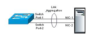
NICs trunked together can also provide network links beyond the throughput of any one single NIC. For example, this allows a central file server to establish an aggregate 2-gigabit connection using two 1-gigabit NICs teamed together. Note the data signaling rate will still be 1Gbit/s, which can be misleading depending on methodologies used to test throughput after link aggregation is employed.
Microsoft Windows
Microsoft Windows does support native link aggregation starting from Windows Server 2012. For the previous Windows Server versions, however, some manufacturers provide software for aggregation on their multiport NICs at the device-driver layer. Intel, for example, has released a package for Windows called Advanced Networking Services (ANS) to bond Intel Fast Ethernet and Gigabit cards. Nvidia also supports "teaming" with their Nvidia Network Access Manager/Firewall Tool. HP also has a teaming tool for HP branded NICs which will allow for non-EtherChanneled NIC teaming or which will support several modes of EtherChannel (port aggregation) including 802.3ad with LACP. In addition, there is a basic layer-3 aggregation (available at least from Windows XP SP3), that allows servers with multiple IP interfaces on the same network to perform load balancing, and home users with more than one internet connection, to increase connection speed by sharing the load on all interfaces. Broadcom offers advanced functions via Broadcom Advanced Control Suite (BACS), via which the teaming functionality of BASP ("Broadcom Advanced Server Program") is available, offering 802.3ad static LAGs, LACP, and "smart teaming" which doesn't require any configuration on the switches to work. It is possible to configure teaming with BACS with a mix of NICs from different vendors as long as at least one of them is Broadcom and the other NICs have the required capabilities to create teaming.
Linux and UNIX
Linux, FreeBSD, NetBSD, OpenBSD, Mac OS X, OpenSolaris and commercial Unix distributions such as AIX implement Ethernet bonding (trunking) at a higher level, and can hence deal with NICs from different manufacturers or drivers, as long as the NIC is supported by the kernel.
Virtualization platforms
Citrix XenServer and VMware ESX have native support for link-aggregation. XenServer offers both static-LAG's as well as LACP. vSphere 5.1 (ESXi) now supports both static-LAG's and LACP natively with their virtual distributed switch. For Microsoft's Hyper-V bonding or teaming isn't offered from the hyper-visor or OS-level, but the above-mentioned methods for teaming under Windows applies to Hyper-V as well.
Limitations
Single switch
With modes balance-rr, balance-xor, broadcast and 802.3ad all physical ports in the link aggregation group must reside on the same logical switch, which in most scenarios will leave a single point of failure when the physical switch to which both links are connected goes offline. Modes active-backup, balance-tlb, and balance-alb can also be set up with two or more switches. But after failover (like all other modes), in some cases, active sessions may fail (due to ARP problems) and have to be restarted.
However, almost all vendors have proprietary extensions that resolve some of this issue: they aggregate multiple physical switches into one logical switch. In 2012, the IEEE standardized this feature in IEEE 802.1aq. The Split multi-link trunking (SMLT) protocol allows multiple Ethernet links to be split across multiple switches in a stack, preventing any single point of failure, and additionally allowing all switches to be load balanced across multiple aggregation switches from the single access stack. These devices synchronize state across an Inter-Switch Trunk (IST) such that they appear to the connecting (access) device to be a single device (switch block) and prevent any packet duplication. SMLT provides enhanced resiliency with sub-second failover and sub-second recovery for all speed trunks (10 Mbit/s, 100 Mbit/s, 1,000 Mbit/s, and 10 Gbit/s) while operating transparently to end-devices.
Same link speed
In most implementations, all the ports used in an aggregation consist of the same physical type, such as all copper ports (10/100/1000BASE?T), all multi-mode fiber ports, or all single-mode fiber ports. However, all the IEEE standard requires is that each link be full duplex and all of them have an identical speed (10, 100, 1,000 or 10,000 Mbit/s).
Many switches are PHY independent, meaning that a switch could have a mixture of copper, SX, LX, LX10 or other GBICs. While maintaining the same PHY is the usual approach, it is possible to aggregate a 1000BASE-SX fiber for one link and a 1000BASE-LX (longer, diverse path) for the second link, but the important thing is that the speed will be 1 Gbit/s full duplex for both links. One path may have a slightly longer transit time but the standard has been engineered so this will not cause an issue.
Ethernet aggregation mismatch
Aggregation mismatch refers to not matching the aggregation type on both ends of the link. Some switches do not implement the 802.1AX standard but support static configuration of link aggregation. Therefore, link aggregation between similarly statically configured switches will work, but will fail between a statically configured switch and a device that is configured for LACP.