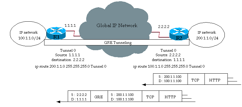
Generic Routing Encapsulation (GRE) is a tunneling protocol developed by Cisco Systems that can encapsulate a wide variety of network layer protocols inside virtual point-to-point links over an Internet Protocol network.
Example uses
- In conjunction with PPTP to create VPNs.
- In conjunction with IPsec VPNs to allow passing of routing information between connected networks.
- In Mobility protocols.
- In A8/A10 interfaces to encapsulate IP data to/from Packet Control Function (PCF).
- Linux and BSD can establish ad-hoc IP over GRE tunnels which are interoperable with Cisco equipment.
- Distributed denial of service (DDoS) protected appliance to an unprotected endpoint.
Example protocol stack
| OSI model layer | Protocol |
|---|---|
| 5. Session | X.225 |
| 4. Transport | UDP |
| 3. Network (GRE-encapsulated) | IPv6 |
| Encapsulation | GRE |
| 3. Network | IPv4 |
| 2. Data Link | Ethernet |
| 1. Physical | Ethernet physical layer |
Based on the principles of protocol layering in OSI, protocol encapsulation, not specifically GRE, breaks the layering order. It may be viewed as a separator between two different protocol stacks, one acting as a carrier for another.
IP as a delivery protocol
GRE packets that are encapsulated within IP use IP protocol type 47.
Packet header
Standard GRE Packet Header
A standard GRE packet header structure, as defined by RFC 2784 and RFC 2890, is represented in the diagram below.
| Bits 0–3 | 4–12 | 13–15 | 16–31 | |||
|---|---|---|---|---|---|---|
| C | K | S | Reserved0 | Version | Protocol Type | |
| Checksum (optional) | Reserved1 (optional) | |||||
| Key (optional) | ||||||
| Sequence Number (optional) |
CChecksum bit. Set to 1 if a checksum is present. KKey bit. Set to 1 if a key is present. SSequence number bit. Set to 1 if a sequence number is present. Reserved0Reserved bits; set to 0. VersionGRE Version number; set to 0. Protocol TypeIndicates the ether protocol type of the encapsulated payload. (For IPv4, this would be hex 0800.) ChecksumPresent if the C bit is set; contains the checksum for the GRE header and payload. Reserved1Present if the C bit is set; is set to 0. KeyPresent if the K bit is set; contains an application-specific key value. Sequence NumberPresent if the S bit is set; contains a sequence number for the GRE packet.
PPTP GRE Packet Header
The Point-to-Point Tunneling Protocol (PPTP), defined in RFC 2637, uses a variant GRE packet header structure, represented below. PPTP creates a GRE tunnel through which the PPTP GRE packets are sent.
| Bits 0–4 | 5–7 | 8 | 9-12 | 13–15 | 16–31 | ||||
|---|---|---|---|---|---|---|---|---|---|
| C | R | K | S | s | Recur | A | Flags | Version | Protocol Type |
| Key Payload Length | Key Call ID | ||||||||
| Sequence Number (optional) | |||||||||
| Acknowledgement Number (optional) |
CChecksum bit. For PPTP GRE packets, this is set to 0. RRouting bit. For PPTP GRE packets, this is set to 0. KKey bit. For PPTP GRE packets, this is set to 1. (All PPTP GRE packets carry a key.) SSequence number bit. Set to 1 if a sequence number is supplied, indicating a PPTP GRE data packet. sStrict source route bit. For PPTP GRE packets, this is set to 0. RecurRecursion control bits. For PPTP GRE packets, these are set to 0. AAcknowledgement number present. Set to 1 if an acknowledgement number is supplied, indicating a PPTP GRE acknowledgement packet. FlagsFlag bits. For PPTP GRE packets, these are set to 0. VersionGRE Version number. For PPTP GRE packets, this is set to 1. Protocol TypeFor PPTP GRE packets, this is set to hex 880B. Key Payload LengthContains the size of the payload, not including the GRE header. Key Call IDContains the Peer's Call ID for the session to which the packet belongs. Sequence NumberPresent if the S bit is set; contains the GRE payload sequence number. Acknowledgement NumberPresent if the A bit is set; contains the sequence number of the highest GRE payload packet received by the sender.

