The process of subnetting involves the separation of the network and subnet portion of an address from the host identifier. This is performed by a bitwise AND operation between the IP address and the (sub)network mask. The result yields the network address or prefix, and the remainder is the host identifier.
Determining the network prefix
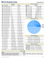
An IPv4 network mask consists of 32 bits, a sequence of ones (1) followed by a block of 0s. The trailing block of zeros (0) designates that part as being the host identifier.
The following example shows the separation of the network prefix and the host identifier from an address (192.168.5.130) and its associated /24 network mask (255.255.255.0). The operation is visualized in a table using binary address formats.
| Binary form | Dot-decimal notation | |
|---|---|---|
| IP address | 11000000.10101000.00000101.10000010 | 192.168.5.130 |
| Subnet mask | 11111111.11111111.11111111.00000000 | 255.255.255.0 |
| Network prefix | 11000000.10101000.00000101.00000000 | 192.168.5.0 |
| Host part | 00000000.00000000.00000000.10000010 | 0.0.0.130 |
The mathematical operation for calculating the network prefix is the bitwise AND of IP address and subnet mask. The result of the operation yields the network prefix 192.168.5.0. The host part 130 can be derived by using bitwise AND of IP address and inverse subnet mask.
Subnetting
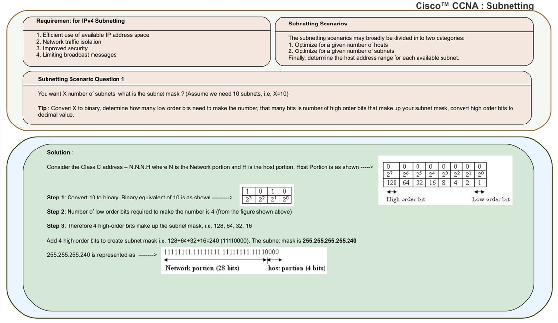
Subnetting is the process of designating some high-order bits from the host part and grouping them with the network mask to form the subnet mask. This divides a network into smaller subnets. The following diagram modifies the example by moving 2 bits from the host part to the subnet mask to form four smaller subnets one quarter the previous size:
| Binary form | Dot-decimal notation | |
|---|---|---|
| IP address | 11000000.10101000.00000101.10000010 | 192.168.5.130 |
| Subnet mask | 11111111.11111111.11111111.11000000 | 255.255.255.192 |
| Network prefix | 11000000.10101000.00000101.10000000 | 192.168.5.128 |
| Host part | 00000000.00000000.00000000.00000010 | 0.0.0.2 |
Special addresses and subnets
Internet Protocol version 4 uses specially designated address formats to facilitate recognition of special address functionality. The first and the last subnets obtained by subnetting have traditionally had a special designation and, early on, special usage implications. In addition, IPv4 uses the all ones host address, i.e. the last address within a network, for broadcast transmission to all hosts on the link.
Subnet zero and the all-ones subnet
The first subnet obtained from subnetting has all bits in the subnet bit group set to zero (0). It is therefore called subnet zero. The last subnet obtained from subnetting has all bits in the subnet bit group set to one (1). It is therefore called the all-ones subnet.
The IETF originally discouraged the production use of these two subnets due to possible confusion of having a network and subnet with the same address. The practice of avoiding subnet zero and the all-ones subnet was declared obsolete in 1995 by RFC 1878, an informational, but now historical document.
Subnet and host counts
The number of subnetworks available, and the number of possible hosts in a network may be readily calculated. In the example (above) two bits were borrowed to create subnetworks, thus creating 4 (22) possible subnets.
| Network | Network (binary) | Broadcast address |
|---|---|---|
192.168.5.0/26 | 11000000.10101000.00000101.00000000 | 192.168.5.63 |
192.168.5.64/26 | 11000000.10101000.00000101.01000000 | 192.168.5.127 |
192.168.5.128/26 | 11000000.10101000.00000101.10000000 | 192.168.5.191 |
192.168.5.192/26 | 11000000.10101000.00000101.11000000 | 192.168.5.255 |
The RFC 950 specification recommended reserving the subnet values consisting of all zeros (see above) and all ones (broadcast), reducing the number of available subnets by two. However, due to the inefficiencies introduced by this convention it was abandoned for use on the public Internet, and is only relevant when dealing with legacy equipment that does not implement CIDR. The only reason not to use the all-zeroes subnet is that it is ambiguous when the prefix length is not available. RFC 950 itself did not make the use of the zero subnet illegal; it was however considered best practice by engineers.
CIDR-compliant routing protocols transmit both length and suffix. RFC 1878 provides a subnetting table with examples.
The remaining bits after the subnet bits are used for addressing hosts within the subnet. In the above example the subnet mask consists of 26 bits, leaving 6 bits for the host identifier. This allows for 62 host combinations (26-2).
The all-zeros value and all-ones values are reserved for the network address and broadcast address respectively. In systems that can handle CIDR a count of two is therefore subtracted from the host availability, rather than the subnet availability, making all 2n subnets available and removing a need to subtract two subnets.
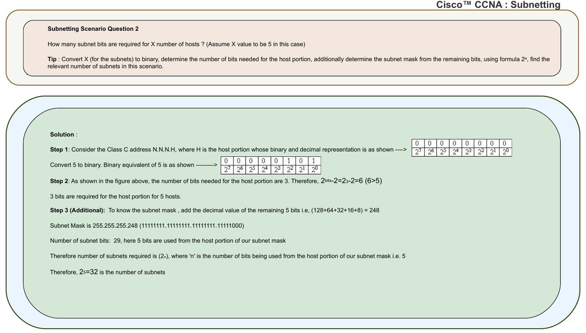
For example, under CIDR /28 all 16 subnets are usable. Each broadcast, i.e. .15 .31 - .255 comes off the client count, not the network, thus making the last subnet also usable.
Only legacy technology not capable of using CIDR default in accordance with the RFC 1878 standard required the subtraction of subnets, one at the beginning of the range and one at the end of the range. Cisco added to this confusion by the use of subtracting from the subnet formula in its publications, for so-called usable subnets up until 2007. Cisco routers, by default, did not allow an IP address belonging to subnet zero to be configured on an interface.
In general the number of available hosts on a subnet is 2h-2, where h is the number of bits used for the host portion of the address. The number of available subnets is 2n, where n is the number of bits used for the network portion of the address. This is the RFC 1878 standard used by the IETF, the IEEE and COMPTIA.
RFC 3021 specifies an exception to this rule for 31-bit subnet masks, which means the host identifier is only one bit long for two permissible addresses. In such networks, usually point-to-point links, only two hosts (the end points) may be connected and a specification of network and broadcast addresses is not necessary.
A /24 network may be divided into the following subnets by increasing the subnet mask successively by one bit. This affects the total number of hosts that can be addressed in the /24 network (last column).
| Prefix size | Network mask | Available subnets | Usable hosts per subnet | Total usable hosts |
|---|---|---|---|---|
| /24 | 255.255.255.0 | 1 | 254 | 254 |
| /25 | 255.255.255.128 | 2 | 126 | 252 |
| /26 | 255.255.255.192 | 4 | 62 | 248 |
| /27 | 255.255.255.224 | 8 | 30 | 240 |
| /28 | 255.255.255.240 | 16 | 14 | 224 |
| /29 | 255.255.255.248 | 32 | 6 | 192 |
| /30 | 255.255.255.252 | 64 | 2 | 128 |
| /31 | 255.255.255.254 | 128 | 2 * | 256 |