In data communications, flow control is the process of managing the rate of data transmission between two nodes to prevent a fast sender from overwhelming a slow receiver. It provides a mechanism for the receiver to control the transmission speed, so that the receiving node is not overwhelmed with data from transmitting node. Flow control should be distinguished from congestion control, which is used for controlling the flow of data when congestion has actually occurred. Flow control mechanisms can be classified by whether or not the receiving node sends feedback to the sending node.
Flow control is important because it is possible for a sending computer to transmit information at a faster rate than the destination computer can receive and process it. This can happen if the receiving computers have a heavy traffic load in comparison to the sending computer, or if the receiving computer has less processing power than the sending computer.
Stop-and-wait
Main article: Stop-and-wait ARQ
Stop-and-wait flow control is the simplest form of flow control. In this method, the receiver indicates its readiness to receive data for each frame, the message is broken into multiple frames. The sender waits for an ACK (acknowledgement) after every frame for specified time (called time out). It is sent to ensure that the receiver has received the frame correctly. It will then send the next frame only after the ACK has been received.
Operations
- Sender: Transmits a single frame at a time.
- Receiver: Transmits acknowledgement (ACK) as it receives a frame.
- Sender receive ACK within time out.
- Go to step 1.
If a frame or ACK is lost during transmission then it has to be transmitted again by sender. This retransmission process is known as ARQ (automatic repeat request).
The problem with Stop-and wait is that only one frame can be transmitted at a time, and that often leads to inefficient transmission, because until the sender receives the ACK it cannot transmit any new packet. During this time both the sender and the channel are unutilised.
Pros and cons of stop and wait
Pros
The only advantage of this method of flow control is its simplicity.
Cons
The sender needs to wait for the ACK after every frame it transmits. This is a source of inefficiency, and is particularly bad when the propagation delay is much longer than the transmission delay.
Stop and wait can also create inefficiencies when sending longer transmissions. When longer transmissions are sent there is more likely chance for error in this protocol. If the messages are short the errors are more likely to be detected early. More inefficiency is created when single messages are broken into separate frames because it makes the transmission longer.
Sliding Window
Main article: Sliding Window Protocol
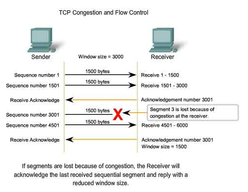
A method of flow control in which a receiver gives a transmitter permission to transmit data until a window is full. When the window is full, the transmitter must stop transmitting until the receiver advertises a larger window.
Sliding-window flow control is best utilized when the buffer size is limited and pre-established. During a typical communication between a sender and a receiver the receiver allocates buffer space for n frames (n is the buffer size in frames). The sender can send and the receiver can accept n frames without having to wait for an acknowledgement. A sequence number is assigned to frames in order to help keep track of those frames which did receive an acknowledgement. The receiver acknowledges a frame by sending an acknowledgement that includes the sequence number of the next frame expected. This acknowledgement announces that the receiver is ready to receive n frames, beginning with the number specified. Both the sender and receiver maintain what is called a window. The size of the window is less than or equal to the buffer size.
Sliding window flow control has a far better performance than stop-and-wait flow control. For example in a wireless environment data rates are very low and noise level is very high, so waiting for an acknowledgement for every packet that is transferred is not very feasible. Therefore, transferring data as a bulk would yield a better performance in terms of higher throughput.
Sliding window flow control is a point to point protocol assuming that no other entity tries to communicate until the current data transfer is complete. The window maintained by the sender indicates which frames he can send. The sender sends all the frames in the window and waits for an acknowledgement (as opposed to acknowledging after every frame). The sender then shifts the window to the corresponding sequence number, thus indicating that frames within the window starting from the current sequence number can be sent.
Go Back N
Main article: Go-Back-N ARQ
An automatic repeat request (ARQ) algorithm, used for error correction, in which a negative acknowledgement (NAK) causes retransmission of the word in error as well as the previous N–1 words. The value of N is usually chosen such that the time taken to transmit the N words is less than the round trip delay from transmitter to receiver and back again. Therefore a buffer is not needed at the receiver.
The normalized propagation delay (a) = propagation time (Tp)?transmission time (Tt), where Tp = Length (L) over propagation velocity (V) and Tt = bitrate (r) over Framerate (F). So that a =LF?Vr.
To get the utilization you must define a window size (N). If N is greater than or equal to 2a + 1 then the utilization is 1 (full utilization) for the transmission channel. If it is less than 2a + 1 then the equation N?1+2a must be used to compute utilization.
Selective Repeat
Main article: Selective Repeat ARQ
Selective Repeat is a connection oriented protocol in which both transmitter and receiver have a window of sequence numbers. The protocol has a maximum number of messages that can be sent without acknowledgement. If this window becomes full, the protocol is blocked until an acknowledgement is received for the earliest outstanding message. At this point the transmitter is clear to send more messages.
Comparison
This section is geared towards the idea of comparing Stop-and-wait, Sliding Window with the subsets of Go Back N and Selective Repeat.
Each equation is a general overview. View each page for more in-depth definition.
Stop-and-wait
Error free: 1/2a+1 With errors: 1-P/1+2a
Selective Repeat
We define throughput T as the average number of blocks communicated per transmitted block. It is more convenient to calculate the average number of transmissions necessary to communicate a block, a quantity we denote by 0, and then to determine T from the equation
T=1/b
Transmit flow control
Transmit flow control may occur:
- between data terminal equipment (DTE) and a switching center, via data circuit-terminating equipment (DCE), the opposite types interconnected straightforwardly,
- or between two devices of the same type (two DTEs, or two DCEs), interconnected by a crossover cable.
The transmission rate may be controlled because of network or DTE requirements. Transmit flow control can occur independently in the two directions of data transfer, thus permitting the transfer rates in one direction to be different from the transfer rates in the other direction. Transmit flow control can be
- either stop-and-wait,
- or use a sliding window.
Flow control can be performed
- either by control signal lines in a data communication interface (see serial port and RS 232),
- or by reserving in-band control characters to signal flow start and stop (such as the ASCII codes for XON/XOFF).
Hardware flow control
In common RS 232 there are pairs of control lines which are usually referred to as hardware flow control:
- RTS (Request To Send) and CTS (Clear To Send), used in RTS flow control
- DTR (Data Terminal Ready) and DSR (Data Set Ready), DTR flow control
Hardware flow control is typically handled by the DTE or "master end", as it is first raising or asserting its line to command the other side:
- In the case of RTS control flow, DTE sets its RTS, which signals the opposite end (the slave end such as a DCE) to begin monitoring its data input line. When ready for data, the slave end will raise its complementary line, CTS in this example, which signals the master to start sending data, and for the master to begin monitoring the slave's data output line. If either end needs to stop the data, it lowers its respective "data readyness" line.
- For PC-to-modem and similar links, in the case of DTR flow control, DTR/DSR are raised for the entire modem session (say a dialup internet call), and RTS/CTS are raised for each block of data.
Software flow control
Main article: Software flow control
Conversely, XON/XOFF is usually referred to as software flow control.
Open-loop flow control
The open-loop flow control mechanism is characterized by having no feedback between the receiver and the transmitter. This simple means of control is widely used. The allocation of resources must be a “prior reservation” or “hop-to-hop” type.
Open-loop flow control has inherent problems with maximizing the utilization of network resources. Resource allocation is made at connection setup using a CAC (Connection Admission Control) and this allocation is made using information that is already “old news” during the lifetime of the connection. Often there is an over-allocation of resources and reserved but unused capacities are wasted. Open-loop flow control is used by ATM in its CBR, VBR and UBR services (see traffic contract and congestion control).
Open-loop flow control incorporates two controls; the controller and a regulator. The regulator is able to alter the input variable in response to the signal from the controller. An open-loop system has no feedback or feed forward mechanism, so the input and output signals are not directly related and there is increased traffic variability. There is also a lower arrival rate in such system and a higher loss rate. In an open control system, the controllers can operate the regulators at regular intervals, but there is no assurance that the output variable can be maintained at the desired level. While it may be cheaper to use this model, the open-loop model can be unstable.
Closed-loop flow control
The closed-loop flow control mechanism is characterized by the ability of the network to report pending network congestion back to the transmitter. This information is then used by the transmitter in various ways to adapt its activity to existing network conditions. Closed-loop flow control is used by ABR (see traffic contract and congestion control). Transmit flow control described above is a form of closed-loop flow control.
This system incorporates all the basic control elements, such as, the sensor, transmitter, controller and the regulator. The sensor is used to capture a process variable. The process variable is sent to a transmitter which translates the variable to the controller. The controller examines the information with respect to a desired value and initiates a correction action if required. The controller then communicates to the regulator what action is needed to ensure that the output variable value is matching the desired value. Therefore there is a high degree of assurance that the output variable can be maintained at the desired level. The closed-loop control system can be a feedback or a feed forward system:
A feedback closed-loop system has a feed-back mechanism that directly relates the input and output signals. The feed-back mechanism monitors the output variable and determines if additional correction is required. The output variable value that is fed backward is used to initiate that corrective action on a regulator. Most control loops in the industry are of the feedback type.
In a feed-forward closed loop system, the measured process variable is an input variable. The measured signal is then used in the same fashion as in a feedback system.
The closed-loop model produces lower loss rate and queuing delays, as well as it results in congestion-responsive traffic. The closed-loop model is always stable, as the number of active lows is bounded.
PC–radio flow control
Flow control also includes the control of data transfer between the PC and the radio. While the PC is transferring data to the modem and if the modem detects a reception, the PC–radio communication must be paused, giving higher priority to the incoming signal.