Open Shortest Path First (OSPF) is a routing protocol for Internet Protocol (IP) networks. It uses a link state routing algorithm and falls into the group of interior routing protocols, operating within a single autonomous system (AS). It is defined as OSPF Version 2 in RFC 2328 (1998) for IPv4. The updates for IPv6 are specified as OSPF Version 3 in RFC 5340 (2008).
OSPF is perhaps the most widely used interior gateway protocol (IGP) in large enterprise networks. Intermediate System to Intermediate System (IS-IS), another link-state dynamic routing protocol, is more common in large service provider networks. The most widely used exterior gateway protocol is the Border Gateway Protocol (BGP), the principal routing protocol between autonomous systems on the Internet.
Overview
OSPF is an interior gateway protocol (IGP) for routing Internet Protocol (IP) packets solely within a single routing domain, such as an autonomous system. It gathers link state information from available routers and constructs a topology map of the network. The topology is presented as a routing table to the Internet Layer which routes datagrams based solely on the destination IP address found in IP packets. OSPF supports Internet Protocol Version 4 (IPv4) and Internet Protocol Version 6 (IPv6) networks and features variable-length subnet masking (VLSM) and Classless Inter-Domain Routing (CIDR) addressing models.
OSPF detects changes in the topology, such as link failures, and converges on a new loop-free routing structure within seconds. It computes the shortest path tree for each route using a method based on Dijkstra's algorithm, a shortest path first algorithm.
The OSPF routing policies for constructing a route table are governed by link cost factors (external metrics) associated with each routing interface. Cost factors may be the distance of a router (round-trip time), data throughput of a link, or link availability and reliability, expressed as simple unitless numbers. This provides a dynamic process of traffic load balancing between routes of equal cost.
An OSPF network may be structured, or subdivided, into routing areas to simplify administration and optimize traffic and resource utilization. Areas are identified by 32-bit numbers, expressed either simply in decimal, or often in octet-based dot-decimal notation, familiar from IPv4 address notation.
By convention, area 0 (zero), or 0.0.0.0, represents the core or backbone area of an OSPF network. The identifications of other areas may be chosen at will; often, administrators select the IP address of a main router in an area as area identification. Each additional area must have a direct or virtual connection to the OSPF backbone area. Such connections are maintained by an interconnecting router, known as area border router (ABR). An ABR maintains separate link state databases for each area it serves and maintains summarized routes for all areas in the network.
OSPF does not use a TCP/IP transport protocol, such as UDP or TCP, but encapsulates its data in IP datagrams with protocol number 89. This is in contrast to other routing protocols, such as the Routing Information Protocol (RIP) and the Border Gateway Protocol (BGP). OSPF implements its own error detection and correction functions.
OSPF uses multicast addressing for route flooding on a broadcast domain. For non-broadcast networks, special provisions for configuration facilitate neighbor discovery. OSPF multicast IP packets never traverse IP routers (never traverse Broadcast Domains), they never travel more than one hop. OSPF is therefore a Link Layer protocol in the Internet Protocol Suite. OSPF reserves the multicast addresses 224.0.0.5 (IPv4) and FF02::5 (IPv6) for all SPF/link state routers (AllSPFRouters) and 224.0.0.6 (IPv4) and FF02::6 (IPv6) for all Designated Routers (AllDRouters), as specified in RFC 2328 and RFC 5340.
For routing multicast IP traffic, OSPF supports the Multicast Open Shortest Path First protocol (MOSPF) as defined in RFC 1584. Cisco does not include MOSPF in their OSPF implementations. PIM (Protocol Independent Multicast) in conjunction with OSPF or other IGPs, is widely deployed.
The OSPF protocol, when running on IPv4, can operate securely between routers, optionally using a variety of authentication methods to allow only trusted routers to participate in routing. OSPFv3, running on IPv6, no longer supports protocol-internal authentication. Instead, it relies on IPv6 protocol security (IPsec).
OSPF version 3 introduces modifications to the IPv4 implementation of the protocol. Except for virtual links, all neighbor exchanges use IPv6 link-local addressing exclusively. The IPv6 protocol runs per link, rather than based on the subnet. All IP prefix information has been removed from the link-state advertisements and from the Hello discovery packet making OSPFv3 essentially protocol-independent. Despite the expanded IP addressing to 128-bits in IPv6, area and router Identifications are still based on 32-bit values.
Router relationships
OSPF supports complex networks with multiple routers, including backup routers, to balance traffic load on multiple links to other subnetworks. Neighboring routers in the same broadcast domain or at each end of a point-to-point telecommunications communicate with each other via the OSPF protocol. Routers form adjacencies when they have detected each other. This detection is initiated when a router identifies itself in a Hello protocol packet. Upon acknowledgment, this establishes a two-way state and is the most basic relationship. The routers in an Ethernet or Frame Relay network select a Designated Router (DR) and a Backup Designated Router (BDR) which act as a hub to reduce traffic between routers. OSPF uses both unicast and multicast transmission modes to send "Hello" packets and link state updates.
As a link state routing protocol, OSPF establishes and maintains neighbor relationships for exchanging routing updates with other routers. The neighbor relationship table is called an adjacency database. An OSPF router forms neighbor relationships only with the routers directly connected to it. For forming a neighbor relationship between, the interfaces used to form the relationship must be in the same OSPF area. Generally an interface is only configured in a single area, however, an interface may be configured to belong to multiple areas. In the second area, such an interface must be configured as a secondary interface.
Adjacency state machine
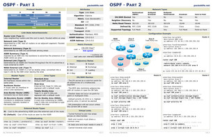
Each OSPF router within a network communicates with other neighboring routers on each connecting interface to establish the states of all adjacencies. Every such communication sequence is a separate conversation identified by the pair of router IDs of the communicating neighbors. RFC 2328 specifies the protocol for initiating these conversations (Hello Protocol) and for establishing full adjacencies (Database Description Packets, Link State Request Packets). During its course, each router conversation transitions through a maximum of eight conditions defined by a state machine:
- Down: The state down represents the initial state of a conversation when no information has been exchanged and retained between routers with the Hello Protocol.
- Attempt: The Attempt state is similar to the Down state, except that a router is in the process of concerted efforts to establish a conversation with another router, but is only used on NBMA networks.
- Init: The Init state indicates that a HELLO packet has been received from a neighbor, but the router has not established a two-way conversation.
- 2-Way: The 2-Way state indicates the establishment of a bidirectional conversation between two routers. This state immediately precedes the establishment of adjacency. This is the lowest state of a router that may be considered as a Designated Router.
- ExStart: The ExStart state is the first step of adjacency of two routers.
- Exchange: In the Exchange state, a router is sending its link state database information to the adjacent neighbor. At this state, a router is capable to exchange all OSPF routing protocol packets.
- Loading: In the Loading state, a router requests the most recent Link-state advertisements (LSAs) from its neighbor discovered in the previous state.
- Full: The Full state concludes the conversation when the routers are fully adjacent, and the state appears in all router- and network-LSAs. The link state databases of the neighbors are fully synchronized.
Protocol messages
Unlike other routing protocols, OSPF does not carry data via a transport protocol, such as the User Datagram Protocol (UDP) or the Transmission Control Protocol (TCP). Instead, OSPF forms IP datagrams directly, packaging them using protocol number 89 for the IP Protocol field. OSPF defines five different message types, for various types of communication:
HelloHello messages are used as a form of greeting, to allow a router to discover other adjacent routers on its local links and networks. The messages establish relationships between neighboring devices (called adjacencies) and communicate key parameters about how OSPF is to be used in the autonomous system or area.Database DescriptionDatabase Description messages contain descriptions of the topology of the autonomous system or area. They convey the contents of the link-state database (LSDB) for the area from one router to another. Communicating a large LSDB may require several messages to be sent by having the sending device designated as a master device and sending messages in sequence, with the slave (recipient of the LSDB information) responding with acknowledgements.Link State RequestThese messages are used by one router to request updated information about a portion of the LSDB from another router. The message specifies exactly which link(s) about which the requesting device wants more current information.Link State UpdateThese messages contain updated information about the state of certain links on the LSDB. They are sent in response to a Link State Request message, and also broadcast or multicast by routers on a regular basis. Their contents are used to update the information in the LSDBs of routers that receive them.Link State AcknowledgmentThese messages provide reliability to the link-state exchange process, by explicitly acknowledging receipt of a Link State Update message.
Area types
An OSPF network is divided into areas that are logical groupings of hosts and networks. An area includes its router having interfaces connected to the network. Each area maintains a separate link state database whose information may be summarized towards the rest of the network by the connecting router. Thus, the topology of an area is unknown outside of the area. This reduces the routing traffic between parts of an autonomous system.
Areas are uniquely identified with 32-bit numbers. The area identifiers are commonly written in the dot-decimal notation, familiar from IPv4 addressing. However, they are not IP addresses and may duplicate, without conflict, any IPv4 address. The area identifiers for IPv6 implementations (OSPFv3) also use 32-bit identifiers written in the same notation. When dotted formatting is omitted, most implementations expand area 1 to the area identifier 0.0.0.1, but some have been known to expand it as 1.0.0.0.
OSPF defines several special area types:
Backbone area
The backbone area (also known as area 0 or area 0.0.0.0) forms the core of an OSPF network. All other areas are connected to it, and inter-area routing happens via routers connected to the backbone area and to their own associated areas. It is the logical and physical structure for the 'OSPF domain' and is attached to all nonzero areas in the OSPF domain. Note that in OSPF the term Autonomous System Boundary Router (ASBR) is historic, in the sense that many OSPF domains can coexist in the same Internet-visible autonomous system, RFC1996 (ASGuidelines 1996, p. 25).
The backbone area is responsible for distributing routing information between nonbackbone areas. The backbone must be contiguous, but it does not need to be physically contiguous; backbone connectivity can be established and maintained through the configuration of virtual links.
All OSPF areas must connect to the backbone area. This connection, however, can be through a virtual link. For example, assume area 0.0.0.1 has a physical connection to area 0.0.0.0. Further assume that area 0.0.0.2 has no direct connection to the backbone, but this area does have a connection to area 0.0.0.1. Area 0.0.0.2 can use a virtual link through the transit area 0.0.0.1 to reach the backbone. To be a transit area, an area has to have the transit attribute, so it cannot be stubby in any way.
Stub area
A stub area is an area which does not receive route advertisements external to the autonomous system (AS) and routing from within the area is based entirely on a default route. An ABR deletes type 4, 5 LSAs from internal routers, sends them a default route of 0.0.0.0 and turns itself into a default gateway. This reduces LSDB and routing table size for internal routers.
Modifications to the basic concept of stub areas exist in the not-so-stubby area (NSSA). In addition, several other proprietary variations have been implemented by systems vendors, such as the totally stubby area (TSA) and the NSSA totally stubby area, both an extension in Cisco Systems routing equipment.
Not-so-stubby area
A not-so-stubby area (NSSA) is a type of stub area that can import autonomous system external routes and send them to other areas, but still cannot receive AS-external routes from other areas. NSSA is an extension of the stub area feature that allows the injection of external routes in a limited fashion into the stub area. A case study simulates an NSSA getting around the Stub Area problem of not being able to import external addresses. It visualizes the following activities: the ASBR imports external addresses with a type 7 LSA, the ABR converts a type 7 LSA to type 5 and floods it to other areas, the ABR acts as an "ASBR" for other areas. The ABRs do not take type 5 LSAs and then convert to type 7 LSAs for the area.
Proprietary extensions
Several vendors (Cisco, Allied Telesis, Juniper, Alcatel-Lucent, Huawei, Quagga), implement the two extensions below for stub and not-so-stubby areas. Although not covered by RFC standards, they are considered by many to be standard features in OSPF implementations.
Totally stubby areaA totally stubby area is similar to a stub area. However, this area does not allow summary routes in addition to not having external routes, that is, inter-area (IA) routes are not summarized into totally stubby areas. The only way for traffic to get routed outside of the area is a default route which is the only Type-3 LSA advertised into the area. When there is only one route out of the area, fewer routing decisions have to be made by the route processor, which lowers system resource utilization. Occasionally, it is said that a TSA can have only one ABR. NSSA totally stubby areaAn addition to the standard functionality of an NSSA, the totally stubby NSSA is an NSSA that takes on the attributes of a TSA, meaning that type 3 and 4 summary routes are not flooded into this type of area. It is also possible to declare an area both totally stubby and not-so-stubby, which means that the area will receive only the default route from area 0.0.0.0, but can also contain an autonomous system boundary router (ASBR) that accepts external routing information and injects it into the local area, and from the local area into area 0.0.0.0. Redistribution into an NSSA area creates a special type of LSA known as type 7, which can exist only in an NSSA area. An NSSA ASBR generates this LSA, and an NSSA ABR router translates it into type 5 LSA which gets propagated into the OSPF domain.
A newly acquired subsidiary is one example of where it might be suitable for an area to be simultaneously not-so-stubby and totally stubby if the practical place to put an ASBR is on the edge of a totally stubby area. In such a case, the ASBR does send externals into the totally stubby area, and they are available to OSPF speakers within that area. In Cisco's implementation, the external routes can be summarized before injecting them into the totally stubby area. In general, the ASBR should not advertise default into the TSA-NSSA, although this can work with extremely careful design and operation, for the limited special cases in which such an advertisement makes sense.
By declaring the totally stubby area as NSSA, no external routes from the backbone, except the default route, enter the area being discussed. The externals do reach area 0.0.0.0 via the TSA-NSSA, but no routes other than the default route enter the TSA-NSSA. Routers in the TSA-NSSA send all traffic to the ABR, except to routes advertised by the ASBR.
Transit area
A transit area is an area with two or more OSPF border routers and is used to pass network traffic from one adjacent area to another. The transit area does not originate this traffic and is not the destination of such traffic.
Router types
OSPF defines the following overlapping categories of routers:
Internal router (IR)An internal router has all its interfaces belonging to the same area.Area border router (ABR)An area border router is a router that connects one or more areas to the main backbone network. It is considered a member of all areas it is connected to. An ABR keeps multiple copies of the link-state database in memory, one for each area to which that router is connected.Backbone router (BR)A backbone router has an interface to the backbone area. Backbone routers may be also area routers, but do not have to be.Autonomous system boundary router (ASBR)An autonomous system boundary router is a router that is connected by using more than one routing protocol and that exchanges routing information with routers autonomous systems. ASBRs typically also run an exterior routing protocol (e.g., BGP), or use static routes, or both. An ASBR is used to distribute routes received from other, external ASs throughout its own autonomous system. An ASBR creates External LSAs for external addresses and floods them to all areas via ABR. Routers in other areas use ABRs as next hops to access external addresses. Then ABRs forward packets to the ASBR that announces the external addresses.
The router type is an attribute of an OSPF process. A given physical router may have one or more OSPF processes. For example, a router that is connected to more than one area, and which receives routes from a BGP process connected to another AS, is both an area border router and an autonomous system boundary router.
Each router has an identifier, customarily written in the dotted decimal format (e.g., 1.2.3.4) of an IP address. This identifier must be established in every OSPF instance. If not explicitly configured, the highest logical IP address will be duplicated as the router identifier. However, since the router identifier is not an IP address, it does not have to be a part of any routable subnet in the network, and often isn't to avoid confusion.
Router attributes
In addition to the four router types, OSPF uses the terms designated router (DR) and backup designated router (BDR), which are attributes of a router interface.
Designated routerA designated router (DR) is the router interface elected among all routers on a particular multiaccess network segment, generally assumed to be broadcast multiaccess. The basic neighbor discovery process (Hello), flooding (224.0.0.6), DR election (priority, RID). Special techniques, often vendor-dependent, may be needed to support the DR function on nonbroadcast multiaccess (NBMA) media. It is usually wise to configure the individual virtual circuits of a NBMA subnet as individual point-to-point lines; the techniques used are implementation-dependent.Backup designated routerA backup designated router (BDR) is a router that becomes the designated router if the current designated router has a problem or fails. The BDR is the OSPF router with second highest priority at the time of the last election.
A given router can have some interfaces that are designated (DR) and others that are backup designated (BDR), and others that are non-designated. If no router is a DR or a BDR on a given subnet, the BDR is first elected, and then a second election is held for the DR. s a step-by-step DR election example: How neighbor list, neighbor state, DR, and BDR are changed when receiving Hello) The DR is elected based on the following default criteria:
- If the priority setting on an OSPF router is set to 0, that means it can NEVER become a DR or BDR (Backup Designated Router).
- When a DR fails and the BDR takes over, there is another election to see who becomes the replacement BDR.
- The router sending the Hello packets with the highest priority wins the election.
- If two or more routers tie with the highest priority setting, the router sending the Hello with the highest RID (Router ID) wins. NOTE: a RID is the highest logical (loopback) IP address configured on a router, if no logical/loopback IP address is set then the Router uses the highest IP address configured on its active interfaces. (e.g. 192.168.0.1 would be higher than 10.1.1.2).
- Usually the router with the second highest priority number becomes the BDR.
- The priority values range between 0 - 255, with a higher value increasing its chances of becoming DR or BDR.
- If a higher priority OSPF router comes online after the election has taken place, it will not become DR or BDR until (at least) the DR and BDR fail.
- If the current DR 'goes down' the current BDR becomes the new DR and a new election takes place to find another BDR. If the new DR then 'goes down' and the original DR is now available, still previously chosen BDR will become DR.
DR's exist for the purpose of reducing network traffic by providing a source for routing updates. The DR maintains a complete topology table of the network and sends the updates to the other routers via multicast. All routers in a multi-access network segment will form a slave/master relationship with the DR. They will form adjacencies with the DR and BDR only. Every time a router sends an update, it sends it to the DR and BDR on the multicast address 224.0.0.6. The DR will then send the update out to all other routers in the area, to the multicast address 224.0.0.5. This way all the routers do not have to constantly update each other, and can rather get all their updates from a single source. The use of multicasting further reduces the network load. DRs and BDRs are always setup/elected on OSPF broadcast networks. DR's can also be elected on NBMA (Non-Broadcast Multi-Access) networks such as Frame Relay or ATM. DRs or BDRs are not elected on point-to-point links (such as a point-to-point WAN connection) because the two routers on either sides of the link must become fully adjacent and the bandwidth between them cannot be further optimized. DR and non-DR routers evolve from 2-way to full adjacency relationships by exchanging DD, Request, and Update.
Routing metrics
OSPF uses path cost as its basic routing metric, which was defined by the standard not to equate to any standard value such as speed, so the network designer could pick a metric important to the design. In practice, it is determined by the speed (bandwidth) of the interface addressing the given route, although that tends to need network-specific scaling factors now that links faster than 100 Mbit/s are common. Cisco uses a metric like 108/bandwidth (the reference value, 108 by default, can be adjusted). So, a 100Mbit/s link will have a cost of 1, a 10Mbit/s a cost of 10 and so on. But for links faster than 100Mbit/s, the cost would be <1.
Metrics, however, are only directly comparable when of the same type. Four types of metrics are recognized. In decreasing preference, these types are (for example, an intra-area route is always preferred to an External route regardless of metric):
- Intra-area
- Inter-area
- External Type 1, which includes both the external path cost and the sum of internal path costs to the ASBR that advertises the route, External Type 2, the value of which is solely that of the external path cost,
Extensions
Traffic engineering
OSPF-TE is an extension to OSPF extending the expressivity to allow for traffic engineering and use on non-IP networks (RFC 3630). More information about the topology can be exchanged using opaque LSA carrying type-length-value elements. These extensions allow OSPF-TE to run completely out of band of the data plane network. This means that it can also be used on non-IP networks, such as optical networks.
OSPF-TE is used in GMPLS networks as a means to describe the topology over which GMPLS paths can be established. GMPLS uses its own path setup and forwarding protocols, once it has the full network map.
In the Resource Reservation Protocol (RSVP), OSPF-TE is used for recording and flooding RSVP signaled bandwidth reservations for label switched paths within the link-state database.
Optical routing
RFC 3717 documents work in optical routing for IP, based on "constraint-based" extensions to OSPF and IS-IS.
OSPF in broadcast and non-broadcast networks
In broadcast multiple-access networks, neighbor adjacency is formed dynamically using multicast hello packets to 224.0.0.5. A DR and BDR are elected normally, and function normally.
For non-broadcast multiple-access networks (NBMA), RFC 2328 defined the following two official modes for OSPF:
- nonbroadcast
- point-to-multipoint
Cisco has defined the following three additional modes for OSPF in NBMA topologies:
- point-to-multipoint nonbroadcast
- broadcast
- point-to-point
Implementations
- Allied Telesis implements OSPFv2 & OSPFv3 in Allied Ware Plus (AW+)
- Arista Networks implements OSPFv2 and OSPFv3
- BIRD implements both OSPFv2 and OSPFv3
- Cisco IOS
- D-Link implements OSPFv2 on Unified Services Router.
- Dell's FTOS implements OSPFv2 and OSPFv3
- Ericsson IPOS
- ExtremeXOS
- GNU Zebra, a GPL routing suite for Unix-like systems supporting OSPF
- Juniper Junos
- Mikrotik RouterOS
- NetWare implements OSPF in its Multi Protocol Routing module.
- OpenBSD includes an OpenOSPFD implementation within the OpenBGPD protocol.
- Quagga, a fork of GNU Zebra for Unix-like systems
- XORP, a routing suite implementing RFC2328 (OSPFv2) and RFC2740 (OSPFv3) for both IPv4 and IPv6
- Windows NT 4.0 Server, Windows 2000 Server and Windows Server 2003 implement OSPFv2 in the Routing and Remote Access Service, although the functionality was removed in Windows Server 2008.
Applications
OSPF was the first widely deployed routing protocol that could converge a network in the low seconds, and guarantee loop-free paths. It has many features that allow the imposition of policies about the propagation of routes that it may be appropriate to keep local, for load sharing, and for selective route importing more than IS-IS. IS-IS, in contrast, can be tuned for lower overhead in a stable network, the sort more common in ISP than enterprise networks. There are some historical accidents that made IS-IS the preferred IGP for ISPs, but ISP's today may well choose to use the features of the now-efficient implementations of OSPF, after first considering the pros and cons of IS-IS in service provider environments.
As mentioned, OSPF can provide better load-sharing on external links than other IGPs. When the default route to an ISP is injected into OSPF from multiple ASBRs as a Type I external route and the same external cost specified, other routers will go to the ASBR with the least path cost from its location. This can be tuned further by adjusting the external cost.
In contrast, if the default route from different ISPs is injected with different external costs, as a Type II external route, the lower-cost default becomes the primary exit and the higher-cost becomes the backup only.
The only real limiting factor that may compel major ISPs to select IS-IS over OSPF is if they have a network with more than 850 routers. There is mention of an OSPF network with over 1000 routers, but that is quite uncommon and the network must be specifically designed to minimize overhead to achieve stable operation.