In computer networking a routing table, or routing information base (RIB), is a data table stored in a router or a networked computer that lists the routes to particular network destinations, and in some cases, metrics (distances) associated with those routes. The routing table contains information about the topology of the network immediately around it. The construction of routing tables is the primary goal of routing protocols. Static routes are entries made in a routing table by non-automatic means and which are fixed rather than being the result of some network topology "discovery" procedure.
Basics
A routing table uses the same idea that one does when using a map in package delivery. Whenever a node needs to send data to another node on a network, it must first know where to send it. If the node cannot directly connect to the destination node, it has to send it via other nodes along a proper route to the destination node. Most nodes do not try to figure out which route(s) might work; instead, a node will send an IP packet to a gateway in the LAN, which then decides how to route the "package" of data to the correct destination. Each gateway will need to keep track of which way to deliver various packages of data, and for this it uses a Routing Table. A routing table is a database which keeps track of paths, like a map, and allows the gateway to provide this information to the node requesting the information.
With hop-by-hop routing, each routing table lists, for all reachable destinations, the address of the next device along the path to that destination: the next hop. Assuming that the routing tables are consistent, the simple algorithm of relaying packets to their destination's next hop thus suffices to deliver data anywhere in a network. Hop-by-hop is the fundamental characteristic of the IP Internetwork Layer and the OSI Network Layer.
The primary function of a router is to forward a packet toward its destination network, which is the destination IP address of the packet. To do this, a router needs to search the routing information stored in its routing table.
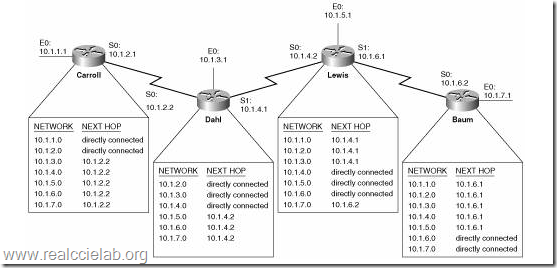
A routing table is a data file in RAM that is used to store route information about directly connected and remote networks. The routing table contains network/next hop associations. These associations tell a router that a particular destination can be optimally reached by sending the packet to a specific router that represents the "next hop" on the way to the final destination. The next hop association can also be the outgoing or exit interface to the final destination.
The network/exit-interface association can also represent the destination network address of the IP packet. This association occurs on the router's directly connected networks.
A directly connected network is a network that is directly attached to one of the router interfaces. When a router interface is configured with an IP address and subnet mask, the interface becomes a host on that attached network. The network address and subnet mask of the interface, along with the interface type and number, are entered into the routing table as a directly connected network. When a router forwards a packet to a host, such as a web server, that host is on the same network as a router's directly connected network.
A remote network is a network that is not directly connected to the router. In other words, a remote network is a network that can only be reached by sending the packet to another router. Remote networks are added to the routing table using either a dynamic routing protocol or by configuring static routes. Dynamic routes are routes to remote networks that were learned automatically by the router, using a dynamic routing protocol. Static routes are routes to networks that a network administrator manually configured.
Difficulties with routing tables
The need to record routes to large numbers of devices using limited storage space represents a major challenge in routing table construction. In the Internet, the currently dominant address aggregation technology is a bitwise prefix matching scheme called Classless Inter-Domain Routing (CIDR).
Contents of routing tables
The routing table consists of at least three information fields:
- the network id: i.e. the destination subnet
- cost/metric: i.e. the cost or metric of the path through which the packet is to be sent
- next hop: The next hop, or gateway, is the address of the next station to which the packet is to be sent on the way to its final destination
Depending on the application and implementation, it can also contain additional values that refine path selection:
- quality of service associated with the route. For example, the U flag indicates that an IP route is up.
- links to filtering criteria/access lists associated with the route
- interface: such as eth0 for the first Ethernet card, eth1 for the second Ethernet card, etc.
Routing tables are also a key aspect of certain security operations, such as unicast reverse path forwarding (uRPF). In this technique, which has several variants, the router also looks up, in the routing table, the source address of the packet. If there exists no route back to the source address, the packet is assumed to be malformed or involved in a network attack, and is dropped.
| Network id | Cost | Next hop |
|---|---|---|
| ........ | ........ | ........ |
| ........ | ........ | ........ |
Shown below is an example of what the table above could look like on an average computer connected to the internet via a home router:
| Network Destination | Netmask | Gateway | Interface | Metric |
|---|---|---|---|---|
| 0.0.0.0 | 0.0.0.0 | 192.168.0.1 | 192.168.0.100 | 10 |
| 127.0.0.0 | 255.0.0.0 | 127.0.0.1 | 127.0.0.1 | 1 |
| 192.168.0.0 | 255.255.255.0 | 192.168.0.100 | 192.168.0.100 | 10 |
| 192.168.0.100 | 255.255.255.255 | 127.0.0.1 | 127.0.0.1 | 10 |
| 192.168.0.1 | 255.255.255.255 | 192.168.0.100 | 192.168.0.100 | 10 |
- The column Network Destination and Netmask together describe the Network id as mentioned earlier. For example, destination 192.168.0.0 and netmask 255.255.255.0 can be written as network id 192.168.0.0/24.
- The Gateway column contains the same information as the Next hop, i.e. it points to the gateway through which the network can be reached.
- The Interface indicates what locally available interface is responsible for reaching the gateway. In this example, gateway 192.168.0.1 (the internet router) can be reached through the local network card with address 192.168.0.100.
- Finally, the Metric indicates the associated cost of using the indicated route. This is useful for determining the efficiency of a certain route from two points in a network. In this example, it is more efficient to communicate with the computer itself through the use of address 127.0.0.1 (called “localhost”) than it would be through 192.168.0.100 (the IP address of the local network card).
Forwarding table
Main article: Forwarding table
Routing tables are generally not used directly for packet forwarding in modern router architectures; instead, they are used to generate the information for a smaller forwarding table. A forwarding table contains only the routes which are chosen by the routing algorithm as preferred routes for packet forwarding. It is often in a compressed or pre-compiled format that is optimized for hardware storage and lookup.
This router architecture separates the Control Plane function of the routing table from the Forwarding Plane function of the forwarding table. This separation of control and forwarding provides uninterrupted performance.