IEEE 802.11n-2009, commonly shortened to 802.11n, is a wireless networking standard that uses multiple antennas to increase data rates. It is an amendment to the IEEE 802.11-2007 wireless networking standard. Its purpose is to improve network throughput over the two previous standards—802.11a and 802.11g—with a significant increase in the maximum net data rate from 54 Mbit/s to 600 Mbit/s (slightly higher gross bit rate including for example error-correction codes, and slightly lower maximum throughput) with the use of four spatial streams at a channel width of 40 MHz. 802.11n standardized support for multiple-input multiple-output, frame aggregation, and security improvements, among other features. It can be used in the 2.4 GHz or 5 GHz frequency bands.
802.11 is a set of IEEE standards that govern wireless networking transmission methods. They are commonly used today in their 802.11a, 802.11b, 802.11g, 802.11n, and 802.11ac versions to provide wireless connectivity in homes and businesses. Development of 802.11n began in 2002, seven years before publication. The 802.11n protocol is now Clause 20 of the published IEEE 802.11-2012 standard.
Description
IEEE 802.11n is an amendment to IEEE 802.11-2007 as amended by IEEE 802.11k-2008, IEEE 802.11r-2008, IEEE 802.11y-2008, and IEEE 802.11w-2009, and builds on previous 802.11 standards by adding multiple-input multiple-output (MIMO) and 40 MHz channels to the PHY (physical layer), and frame aggregation to the MAC layer.
MIMO is a technology that uses multiple antennas to coherently resolve more information than possible using a single antenna. One way it provides this is through Spatial Division Multiplexing (SDM), which spatially multiplexes multiple independent data streams, transferred simultaneously within one spectral channel of bandwidth. MIMO SDM can significantly increase data throughput as the number of resolved spatial data streams is increased. Each spatial stream requires a discrete antenna at both the transmitter and the receiver. In addition, MIMO technology requires a separate radio-frequency chain and analog-to-digital converter for each MIMO antenna, making it more expensive to implement than non-MIMO systems.
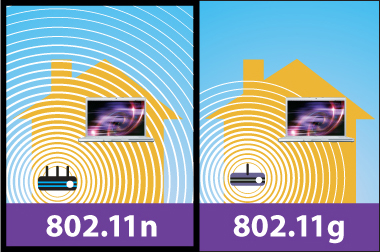
Channels operating with a width of 40 MHz are another feature incorporated into 802.11n; this doubles the channel width from 20 MHz in previous 802.11 PHYs to transmit data, and provides twice the PHY data rate available over a single 20 MHz channel. It can be enabled in the 5 GHz mode, or within the 2.4 GHz mode if there is knowledge that it will not interfere with any other 802.11 or non-802.11 (such as Bluetooth) system using the same frequencies. The MIMO architecture, together with wider-bandwidth channels, offers increased physical transfer rate over 802.11a (5 GHz) and 802.11g (2.4 GHz).
Data encoding
The transmitter and receiver use precoding and postcoding techniques, respectively, to achieve the capacity of a MIMO link. Precoding includes spatial beamforming and spatial coding, where spatial beamforming improves the received signal quality at the decoding stage. Spatial coding can increase data throughput via spatial multiplexing and increase range by exploiting the spatial diversity, through techniques such as Alamouti coding.
Number of antennas
The number of simultaneous data streams is limited by the minimum number of antennas in use on both sides of the link. However, the individual radios often further limit the number of spatial streams that may carry unique data. The a x b : c notation helps identify what a given radio is capable of. The first number (a) is the maximum number of transmit antennas or TX RF chains that can be used by the radio. The second number (b) is the maximum number of receive antennas or RX RF chains that can be used by the radio. The third number (c) is the maximum number of data spatial streams the radio can use. For example, a radio that can transmit on two antennas and receive on three, but can only send or receive two data streams would be 2 x 3 : 2.
The 802.11n draft allows up to 4 x 4 : 4. Common configurations of 11n devices are 2 x 2 : 2; 2 x 3 : 2; and 3 x 2 : 2. All three configurations have the same maximum throughputs and features, and differ only in the amount of diversity the antenna systems provide. In addition, a fourth configuration, 3 x 3 : 3 is becoming common, which has a higher throughput, due to the additional data stream.
Data rates
Assuming equal operating parameters to an 802.11g network achieving 54 megabits per second (on a single 20 MHz channel with one antenna), an 802.11n network can achieve 72 megabits per second (on a single 20 MHz channel with one antenna and 400 ns guard interval); 802.11n's speed may go up to 150 megabits per second if there aren't other Bluetooth, microwave or WiFi emissions in the neighborhood by using two 20 MHz channels in 40 MHz mode. If more antennas are used, then 802.11n can go up to 288 megabits per second in 20 MHz mode with four antennas, or 600 megabits per second in 40 MHz mode with four antennas and 400 ns guard interval. Because the 2.4 GHz band is seriously congested in most urban areas, 802.11n networks usually have more success in increasing data rate by utilizing more antennas in 20 MHz mode rather than by operating in the 40 MHz mode, as the 40 MHz mode requires a relatively free radio spectrum which is only available in rural areas away from cities. Thus, network engineers installing an 802.11n network should strive to select routers and wireless clients with the most antennas possible (one, two, three or four as specified by the 802.11n standard) and try to make sure that the network's bandwidth will be satisfactory even on the 20 MHz mode.
Data rates up to 600 Mbit/s are achieved only with the maximum of four spatial streams using one 40 MHz-wide channel. Various modulation schemes and coding rates are defined by the standard and are represented by a Modulation and Coding Scheme (MCS) index value. The table below shows the relationships between the variables that allow for the maximum data rate. GI (Guard Interval) : Timing between symbols.
20 MHz channel uses an FFT of 64, of which: 56 OFDM subcarriers, 52 are for data and 4 are pilot tones with a carrier separation of 0.3125 MHz (20 MHz/64) (3.2 µs). Each of these subcarriers can be a BPSK, QPSK, 16-QAM or 64-QAM. The total bandwidth is 20 MHz with an occupied bandwidth of 17.8 MHz. Total symbol duration is 3.6 or 4 microseconds, which includes a guard interval of 0.4 or 0.8 microseconds.
| MCS index | Spatial streams | Modulation type | Coding rate | Data rate (Mbit/s) | |||
|---|---|---|---|---|---|---|---|
| 20 MHz channel | 40 MHz channel | ||||||
| 800 ns GI | 400 ns GI | 800 ns GI | 400 ns GI | ||||
| 0 | 1 | BPSK | 1/2 | 6.5 | 7.2 | 13.5 | 15 |
| 1 | 1 | QPSK | 1/2 | 13 | 14.4 | 27 | 30 |
| 2 | 1 | QPSK | 3/4 | 19.5 | 21.7 | 40.5 | 45 |
| 3 | 1 | 16-QAM | 1/2 | 26 | 28.9 | 54 | 60 |
| 4 | 1 | 16-QAM | 3/4 | 39 | 43.3 | 81 | 90 |
| 5 | 1 | 64-QAM | 2/3 | 52 | 57.8 | 108 | 120 |
| 6 | 1 | 64-QAM | 3/4 | 58.5 | 65 | 121.5 | 135 |
| 7 | 1 | 64-QAM | 5/6 | 65 | 72.2 | 135 | 150 |
| 8 | 2 | BPSK | 1/2 | 13 | 14.4 | 27 | 30 |
| 9 | 2 | QPSK | 1/2 | 26 | 28.9 | 54 | 60 |
| 10 | 2 | QPSK | 3/4 | 39 | 43.3 | 81 | 90 |
| 11 | 2 | 16-QAM | 1/2 | 52 | 57.8 | 108 | 120 |
| 12 | 2 | 16-QAM | 3/4 | 78 | 86.7 | 162 | 180 |
| 13 | 2 | 64-QAM | 2/3 | 104 | 115.6 | 216 | 240 |
| 14 | 2 | 64-QAM | 3/4 | 117 | 130 | 243 | 270 |
| 15 | 2 | 64-QAM | 5/6 | 130 | 144.4 | 270 | 300 |
| 16 | 3 | BPSK | 1/2 | 19.5 | 21.7 | 40.5 | 45 |
| 17 | 3 | QPSK | 1/2 | 39 | 43.3 | 81 | 90 |
| 18 | 3 | QPSK | 3/4 | 58.5 | 65 | 121.5 | 135 |
| 19 | 3 | 16-QAM | 1/2 | 78 | 86.7 | 162 | 180 |
| 20 | 3 | 16-QAM | 3/4 | 117 | 130 | 243 | 270 |
| 21 | 3 | 64-QAM | 2/3 | 156 | 173.3 | 324 | 360 |
| 22 | 3 | 64-QAM | 3/4 | 175.5 | 195 | 364.5 | 405 |
| 23 | 3 | 64-QAM | 5/6 | 195 | 216.7 | 405 | 450 |
| 24 | 4 | BPSK | 1/2 | 26 | 28.8 | 54 | 60 |
| 25 | 4 | QPSK | 1/2 | 52 | 57.6 | 108 | 120 |
| 26 | 4 | QPSK | 3/4 | 78 | 86.8 | 162 | 180 |
| 27 | 4 | 16-QAM | 1/2 | 104 | 115.6 | 216 | 240 |
| 28 | 4 | 16-QAM | 3/4 | 156 | 173.2 | 324 | 360 |
| 29 | 4 | 64-QAM | 2/3 | 208 | 231.2 | 432 | 480 |
| 30 | 4 | 64-QAM | 3/4 | 234 | 260 | 486 | 540 |
| 31 | 4 | 64-QAM | 5/6 | 260 | 288.8 | 540 | 600 |
| 32 | 1 | BPSK | 1/2 + Dup ch. | N/A | N/A | 6.0 | 6.7 |
| 33 - 38 | 2 | Asymmetric mod. | Varies | Varies | Varies | Varies | |
| 39 - 52 | 3 | Asymmetric mod. | Varies | Varies | Varies | Varies | |
| 53 - 76 | 4 | Asymmetric mod. | Varies | Varies | Varies | Varies | |
| 77 - 127 | (reserved) | N/A | N/A | N/A | N/A |
Frame aggregation
PHY level data rate improvements do not increase user level throughput beyond a point because of 802.11 protocol overheads, like the contention process, interframe spacing, PHY level headers (Preamble + PLCP) and acknowledgment frames. The main media access control (MAC) feature that provides a performance improvement is aggregation. Two types of aggregation are defined:
- Aggregation of MAC service data units (MSDUs) at the top of the MAC (referred to as MSDU aggregation or A-MSDU)
- Aggregation of MAC protocol data units (MPDUs) at the bottom of the MAC (referred to as MPDU aggregation or A-MPDU)
Frame aggregation is a process of packing multiple MSDUs or MPDUs together to reduce the overheads and average them over multiple frames, thereby increasing the user level data rate. A-MPDU aggregation requires the use of block acknowledgement or BlockAck, which was introduced in 802.11e and has been optimized in 802.11n.
Backward compatibility
When 802.11g was released to share the band with existing 802.11b devices, it provided ways of ensuring coexistence between legacy and successor devices. 802.11n extends the coexistence management to protect its transmissions from legacy devices, which include 802.11g, 802.11b and 802.11a. There are MAC and PHY level protection mechanisms as listed below:
- PHY level protection: Mixed Mode Format protection (also known as L-SIG TXOP Protection): In mixed mode, each 802.11n transmission is always embedded in an 802.11a or 802.11g transmission. For 20 MHz transmissions, this embedding takes care of the protection with 802.11a and 802.11g. However, 802.11b devices still need CTS protection.
- PHY level protection: Transmissions using a 40 MHz channel in the presence of 802.11a or 802.11g clients require using CTS protection on both 20 MHz halves of the 40 MHz channel, to prevent interference with legacy devices.
- MAC level protection: An RTS/CTS frame exchange or CTS frame transmission at legacy rates can be used to protect subsequent 11n transmission.
Even with protection, large discrepancies can exist between the throughput an 802.11n device can achieve in a greenfield network, compared to a mixed-mode network, when legacy devices are present. This is an extension of the 802.11b/802.11g coexistence problem.
Deployment strategies
To achieve maximum output, a pure 802.11n 5 GHz network is recommended. The 5 GHz band has substantial capacity due to many non-overlapping radio channels and less radio interference as compared to the 2.4 GHz band. An 802.11n-only network may be impractical for many users because they need to support legacy equipment that still is 802.11b/g only. In a mixed-mode system, an optimal solution would be to use a dual-radio access point and place the 802.11b/g traffic on the 2.4 GHz radio and the 802.11n traffic on the 5 GHz radio. This setup assumes that all the 802.11n clients are 5 GHz capable, which isn't a requirement of the standard. Quite a few wifi-capable devices only support the 2.4 GHz and there is no practical way to upgrade them to support 5 GHz. A technique called "band steering" is used by some enterprise-grade APs to send 802.11n clients to the 5 GHz band, leaving the 2.4 GHz band for legacy clients. Band steering works by responding only to 5 GHz association requests and not the 2.4 GHz requests from dual-band clients.
40 MHz in 2.4 GHz
The 2.4 GHz ISM band is fairly congested. With 802.11n, there is the option to double the bandwidth per channel to 40 MHz which results in slightly more than double the data rate. However, when in 2.4 GHz, enabling this option takes up to 82% of the unlicensed band, which in many areas may prove to be infeasible.
The specification calls for requiring one primary 20 MHz channel as well as a secondary adjacent channel spaced ±20 MHz away. The primary channel is used for communications with clients incapable of 40 MHz mode. When in 40 MHz mode, the center frequency is actually the mean of the primary and secondary channels.
| Primary channel | 20 MHz | 40 MHz above | 40 MHz below | ||||
|---|---|---|---|---|---|---|---|
| Blocks | 2nd ch. | Center | Blocks | 2nd ch. | Center | Blocks | |
| 1 | 1–3 | 5 | 3 | 1–7 | Not Available | ||
| 2 | 1–4 | 6 | 4 | 1–8 | Not Available | ||
| 3 | 1–5 | 7 | 5 | 1–9 | Not Available | ||
| 4 | 2–6 | 8 | 6 | 2–10 | Not Available | ||
| 5 | 3–7 | 9 | 7 | 3–11 | 1 | 3 | 1–7 |
| 6 | 4–8 | 10 | 8 | 4–12 | 2 | 4 | 1–8 |
| 7 | 5–9 | 11 | 9 | 5–13 | 3 | 5 | 1–9 |
| 8 | 6–10 | 12 | 10 | 6–13 | 4 | 6 | 2–10 |
| 9 | 7–11 | 13 | 11 | 7–13 | 5 | 7 | 3–11 |
| 10 | 8–12 | Not Available | 6 | 8 | 4–12 | ||
| 11 | 9–13 | Not Available | 7 | 9 | 5–13 | ||
| 12 | 10–13 | Not Available | 8 | 10 | 6–13 | ||
| 13 | 11–13 | Not Available | 9 | 11 | 7–13 |
Local regulations may restrict certain channels from operation. For example, Channels 12 and 13 are normally unavailable for use as either a primary or secondary channel in North America. For further information, see List of WLAN channels.
Wi-Fi Alliance
As of mid-2007, the Wi-Fi Alliance started certifying products based on IEEE 802.11n draft 2.0. This certification program established a set of features and a level of interoperability across vendors supporting those features, thus providing one definition of 'draft n'. The baseline certification covers both 20 MHz and 40 MHz wide channels, and up to two spatial streams, for maximum throughputs of 144.4 Mbit/s for 20 MHz and 300 Mbit/s for 40 MHz (with short guard interval). A number of vendors in both the consumer and enterprise spaces have built products that have achieved this certification. The Wi-Fi Alliance certification program subsumed the previous industry consortium efforts to define 802.11n, such as the now dormant Enhanced Wireless Consortium (EWC). The Alliance has upgraded its suite of compatibility tests for some enhancements that were finalized after draft 2.0. Furthermore, it has affirmed that all draft-n certified products remain compatible with the products conforming to the final standards. The Wi-Fi Alliance is investigating further work on certification of additional features of 802.11n not covered by the baseline certification, including higher numbers of spatial streams (3 or 4), Greenfield Format, PSMP, implicit and explicit beamforming and space-time block coding.
Timeline
The following are milestones in the development of 802.11n:
September 11, 2002The first meeting of the High-Throughput Study Group (HTSG) was held. Earlier in the year, in the Wireless Next Generation standing committee (WNG SC), presentations were heard on why they need change and what the target throughput would be required to justify the amendments. Compromise was reached in May 2002 to delay the start of the Study Group until September to allow 11g to complete major work during the July 2002 session. September 11, 2003The IEEE-SA New Standards Committee (NesCom) approved the Project Authorization Request (PAR) for the purpose of amending the 802.11-2007 standard. The new 802.11 Task Group (TGn) is to develop a new amendment. The TGn amendment is based on IEEE Std 802.11-2007, as amended by IEEE Std 802.11k-2008, IEEE Std 802.11r-2008, IEEE Std 802.11y-2008 and IEEE P802.11w. TGn will be the 5th amendment to the 802.11-2007 standard. The scope of this project is to define an amendment that shall define standardized modifications to both the 802.11 physical layers (PHY) and the 802.11 Medium Access Control Layer (MAC) so that modes of operation can be enabled that are capable of much higher throughputs, with a maximum throughput of at least 100 Mbit/s, as measured at the MAC data service access point (SAP). September 15, 2003The first meeting of the new 802.11 Task Group (TGn). May 17, 2004Call for Proposals was issued. September 13, 200432 first round of proposals were heard. March 2005Proposals were downselected to a single proposal, but there is not a 75% consensus on the one proposal. Further efforts were expended over the next 3 sessions without being able to agree on one proposal. July 2005Previous competitors TGn Sync, WWiSE, and a third group, MITMOT, said that they would merge their respective proposals as a draft. The standardization process was expected to be completed by the second quarter of 2009. January 19, 2006The IEEE 802.11n Task Group approved the Joint Proposal's specification, enhanced by EWC's draft specification. March 2006IEEE 802.11 Working Group sent the 802.11n draft to its first letter ballot, allowing the 500+ 802.11 voters to review the document and suggest bug fixes, changes, and improvements. May 2, 2006The IEEE 802.11 Working Group voted not to forward draft 1.0 of the proposed 802.11n standard. Only 46.6% voted to approve the ballot. To proceed to the next step in the IEEE standards process, a majority vote of 75% is required. This letter ballot also generated approximately 12,000 comments—many more than anticipated. November 2006TGn voted to accept draft version 1.06, incorporating all accepted technical and editorial comment resolutions prior to this meeting. An additional 800 comment resolutions were approved during the November session which will be incorporated into the next revision of the draft. As of this meeting, three of the 18 comment topic ad hoc groups chartered in May had completed their work, and 88% of the technical comments had been resolved, with approximately 370 remaining. January 19, 2007The IEEE 802.11 Working Group unanimously (100 yes, 0 no, 5 abstaining) approved a request by the 802.11n Task Group to issue a new draft 2.0 of the proposed standard. Draft 2.0 was based on the Task Group's working draft version 1.10. Draft 2.0 was at this point in time the cumulative result of thousands of changes to the 11n document as based on all previous comments. February 7, 2007The results of Letter Ballot 95, a 15-day Procedural vote, passed with 97.99% approval and 2.01% disapproval. On the same day, 802.11 Working Group announced the opening of Letter Ballot 97. It invited detailed technical comments to closed on 9 March 2007. March 9, 2007Letter Ballot 97, the 30-day Technical vote to approve draft 2.0, closed. They were announced by IEEE 802 leadership during the Orlando Plenary on 12 March 2007. The ballot passed with an 83.4% approval, above the 75% minimum approval threshold. There were still approximately 3,076 unique comments, which were to be individually examined for incorporation into the next revision of draft 2. June 25, 2007The Wi-Fi Alliance announced its official certification program for devices based on draft 2.0. September 7, 2007Task Group agreed on all outstanding issues for draft 2.07. Draft 3.0 is authorized, with the expectation that it go to a sponsor ballot in November 2007. November 2007Draft 3.0 approved (240 voted affirmative, 43 negative, and 27 abstained). The editor was authorized to produce draft 3.01. January 2008Draft 3.02 approved. This version incorporates previously approved technical and editorial comments. There remain 127 unresolved technical comments. It was expected that all remaining comments will be resolved and that TGn and WG11 would subsequently release draft 4.0 for working group recirculation ballot following the March meeting. May 2008Draft 4.0 approved. July 2008Draft 5.0 approved and anticipated publication timeline modified. September 2008Draft 6.0 approved. November 2008Draft 7.0 approved. January 2009Draft 7.0 forwarded to sponsor ballot; the sponsor ballot was approved (158 for, 45 against, 21 abstaining); 241 comments were received. March 2009Draft 8.0 proceeded to sponsor ballot recirculation; the ballot passed by an 80.1% majority (75% required) (228 votes received, 169 approve, 42 not approve); 277 members are in the sponsor ballot pool; The comment resolution committee resolved the 77 comments received, and authorized the editor to create a draft 9.0 for further balloting. April 4, 2009Draft 9.0 passed sponsor ballot recirculation; the ballot passed by an 80.7% majority (75% required) (233 votes received, 171 approve, 41 not approve); 277 members are in the sponsor ballot pool; The comment resolution committee is resolving the 23 new comments received, and will authorize the editor to create a new draft for further balloting. May 15, 2009Draft 10.0 passed sponsor ballot recirculation. June 23, 2009Draft 11.0 passed sponsor ballot recirculation. July 17, 2009Final WG Approval passed with 53 approve, 1 against, 6 abstain.Unanimous approval to send Final WG draft 11.0 to RevCom. September 11, 2009RevCom/Standards Board approval. October 29, 2009Published.
Comparison
[hide]
| ||||||||||
|---|---|---|---|---|---|---|---|---|---|---|
| 802.11 protocol | Release date | Fre- quency | Band- width | Stream data rate | Allowable MIMO streams | Modulation | Approximate range | |||
| Indoor | Outdoor | |||||||||
| (GHz) | (MHz) | (Mbit/s) | (m) | (ft) | (m) | (ft) | ||||
| 802.11-1997 | Jun 1997 | 2.4 | 22 | 1, 2 | N/A | DSSS, FHSS | 20 | 66 | 100 | 330 |
| a | Sep 1999 | 5 | 20 | 6, 9, 12, 18, 24, 36, 48, 54 | N/A | OFDM | 35 | 115 | 120 | 390 |
| 3.7 | — | — | 5,000 | 16,000 | ||||||
| b | Sep 1999 | 2.4 | 22 | 1, 2, 5.5, 11 | N/A | DSSS | 35 | 115 | 140 | 460 |
| g | Jun 2003 | 2.4 | 20 | 6, 9, 12, 18, 24, 36, 48, 54 | N/A | OFDM, DSSS | 38 | 125 | 140 | 460 |
| n | Oct 2009 | 2.4/5 | 20 | 7.2, 14.4, 21.7, 28.9, 43.3, 57.8, 65, 72.2 (6.5, 13, 19.5, 26, 39, 52, 58.5, 65) | 4 | OFDM | 70 | 230 | 250 | 820 |
| 40 | 15, 30, 45, 60, 90, 120, 135, 150 (13.5, 27, 40.5, 54, 81, 108, 121.5, 135) | 70 | 230 | 250 | 820 | |||||
| ac | Dec 2013 | 5 | 20 | 7.2, 14.4, 21.7, 28.9, 43.3, 57.8, 65, 72.2, 86.7, 96.3 (6.5, 13, 19.5, 26, 39, 52, 58.5, 65, 78, 86.7) | 8 | 35 | 115 | |||
| 40 | 15, 30, 45, 60, 90, 120, 135, 150, 180, 200 (13.5, 27, 40.5, 54, 81, 108, 121.5, 135, 162, 180) | 35 | 115 | |||||||
| 80 | 32.5, 65, 97.5, 130, 195, 260, 292.5, 325, 390, 433.3 (29.2, 58.5, 87.8, 117, 175.5, 234, 263.2, 292.5, 351, 390) | 35 | 115 | |||||||
| 160 | 65, 130, 195, 260, 390, 520, 585, 650, 780, 866.7 (58.5, 117, 175.5, 234, 351, 468, 702, 780) | 35 | 115 | |||||||
| ad | Dec 2012 | 60 | 2,160 | Up to 6,912 (6.75 Gbit/s) | N/A | OFDM, single carrier, low-power single carrier | 60 | 200 | 100 | 300 |
| ah | Est. 2016 | 0.9 | ||||||||
| aj | Est. 2016 | 45/60 | ||||||||
| ax | Est. 2019 | 2.4/5 | MIMO-OFDM | |||||||
| ay | 2017 | 60 | 8000 | Up to 100 (100 Gbit/s) | 4 | OFDM, single carrier, | 60 | 200 | 1000 | 3000 |
- A1 A2 IEEE 802.11y-2008 extended operation of 802.11a to the licensed 3.7 GHz band. Increased power limits allow a range up to 5,000 m. As of 2009, it is only being licensed in the United States by the FCC.
- B1 B2 B3 B4 B5 B6 Assumes short guard interval (SGI) enabled.
- C1 C2 C3 C4 C5 C6 Assumes short guard interval (SGI) disabled.