A subnetwork, or subnet, is a logical, visible subdivision of an IP network. The practice of dividing a network into two or more networks is called subnetting.
Computers that belong to a subnet are addressed with a common, identical, most-significant bit-group in their IP address. This results in the logical division of an IP address into two fields, a network or routing prefix and the rest field or host identifier. The rest field is an identifier for a specific host or network interface.
The routing prefix is expressed in CIDR notation. It is written as the first address of a network, followed by a slash character (/), and ending with the bit-length of the prefix. For example, 192.168.1.0/24 is the prefix of the Internet Protocol Version 4 network starting at the given address, having 24 bits allocated for the network prefix, and the remaining 8 bits reserved for host addressing. The IPv6 address specification 2001:db8::/32 is a large address block with 296 addresses, having a 32-bit routing prefix. For IPv4, a network is also characterized by its subnet mask, which is the bitmask that when applied by a bitwise AND operation to any IP address in the network, yields the routing prefix. Subnet masks are also expressed in dot-decimal notation like an address. For example, 255.255.255.0 is the network mask for the 192.168.1.0/24 prefix.
Traffic is exchanged (routed) between subnetworks with special gateways (routers) when the routing prefixes of the source address and the destination address differ. A router constitutes the logical or physical boundary between the subnets.
The benefits of subnetting an existing network vary with each deployment scenario. In the address allocation architecture of the Internet using Classless Inter-Domain Routing (CIDR) and in large organizations, it is necessary to allocate address space efficiently. It may also enhance routing efficiency, or have advantages in network management when subnetworks are administratively controlled by different entities in a larger organization. Subnets may be arranged logically in a hierarchical architecture, partitioning an organization's network address space into a tree-like routing structure.
Network addressing and routing
Computers participating in a network such as the Internet each have at least one logical address. Usually this address is unique to each device and can either be configured automatically with the Dynamic Host Configuration Protocol (DHCP) by a network server, manually by an administrator, or automatically by stateless address autoconfiguration.
An address fulfills the functions of identifying the host and locating it on the network. The most common network addressing architecture is Internet Protocol version 4 (IPv4), but its successor, IPv6, has been increasingly deployed since approximately 2006. An IPv4 address consists of 32 bits, for readability written in a form consisting of four decimal octets separated by dots, called dot-decimal notation. An IPv6 address consists of 128 bits written in a hexadecimal notation and grouping 16 bits separated by colons.
For the purpose of network management, an IP address is divided into two logical parts, the network prefix and the host identifier or rest field. All hosts on a subnetwork have the same network prefix. This routing prefix occupies the most-significant bits of the address. The number of bits allocated within a network to the internal routing prefix may vary between subnets, depending on the network architecture. While in IPv6 the prefix must consist of a set of contiguous 1-bits, in IPv4 this is not enforced, though there is no advantage to using non-contiguous 1-bits. The host part is a unique local identification and is either a host number on the local network or an interface identifier.
This logical addressing structure permits the selective routing of IP packets across multiple networks via special gateway computers, called routers, to a destination host if the network prefixes of origination and destination hosts differ, or sent directly to a target host on the local network if they are the same. Routers constitute logical or physical borders between the subnets, and manage traffic between them. Each subnet is served by a designated default router, but may consist internally of multiple physical Ethernet segments interconnected by network switches or network bridges.
The routing prefix of an address is written in a form identical to that of the address itself. This is called the network mask, or subnet mask, of the address. For example, a specification of the most-significant 18 bits of an IPv4 address, 11111111.11111111.11000000.00000000, is written as 255.255.192.0. If this mask designates a subnet within a larger network, it is also called the subnet mask. This form of denoting the network mask, however, is only used for IPv4 networks.
The modern standard form of specification of the network prefix is CIDR notation, used for both IPv4 and IPv6. It counts the number of bits in the prefix and appends that number to the address after a slash (/) character separator:
- 192.168.0.0, netmask 255.255.255.0 is written as 192.168.0.0/24
- In IPv6, 2001:db8::/32 designates the address 2001:db8:: and its network prefix consisting of the most significant 32 bits.
This notation was introduced with Classless Inter-Domain Routing (CIDR) in RFC 4632. In IPv6 this is the only acceptable form to denote network or routing prefixes.
In classful networking in IPv4, prior to the introduction of CIDR, the network prefix could be directly obtained from the IP address, based on its highest order bit sequence. This determined the class (A, B, C) of the address and therefore the network mask. Since the introduction of CIDR, however, assignment of an IP address to a network interface requires two parameters, the address and its network mask.
In IPv4, on-link determination for an IP address is given simply by the address and netmask configuration, as the address cannot be disassociated from the on-link prefix. For IPv6, however, on-link determination is different in detail and requires the Neighbor Discovery Protocol (NDP). IPv6 address assignment to an interface carries no requirement of a matching on-link prefix and vice versa, with the exception of link-local addresses.
While subnetting may improve network performance in an organizational network, it increases routing complexity, since each locally connected subnet must be represented by a separate entry in the routing tables of each connected router. However, by careful design of the network, routes to collections of more distant subnets within the branches of a tree-hierarchy can be aggregated by single routes. Variable-length subnet masking (VLSM) functionality in commercial routers made the introduction of CIDR seamless across the Internet and in enterprise networks.
IPv4 subnetting
The process of subnetting involves the separation of the network and subnet portion of an address from the host identifier. This is performed by a bitwise AND operation between the IP address and the (sub)network mask. The result yields the network address or prefix, and the remainder is the host identifier.
Determining the network prefix
An IPv4 network mask consists of 32 bits, a sequence of ones (1) followed by a block of 0s. The trailing block of zeros (0) designates that part as being the host identifier.
The following example shows the separation of the network prefix and the host identifier from an address (192.168.5.130) and its associated /24 network mask (255.255.255.0). The operation is visualized in a table using binary address formats.
| Binary form | Dot-decimal notation | |
|---|---|---|
| IP address | 11000000.10101000.00000101.10000010 | 192.168.5.130 |
| Subnet mask | 11111111.11111111.11111111.00000000 | 255.255.255.0 |
| Network prefix | 11000000.10101000.00000101.00000000 | 192.168.5.0 |
| Host part | 00000000.00000000.00000000.10000010 | 0.0.0.130 |
The mathematical operation for calculating the network prefix is the bitwise AND of IP address and subnet mask. The result of the operation yields the network prefix 192.168.5.0. The host part 130 can be derived by using bitwise AND of IP address and one's complement of the subnet mask.
Subnetting
Subnetting is the process of designating some high-order bits from the host part and grouping them with the network mask to form the subnet mask. This divides a network into smaller subnets. The following diagram modifies the example by moving 2 bits from the host part to the subnet mask to form four smaller subnets one quarter the previous size:
| Binary form | Dot-decimal notation | |
|---|---|---|
| IP address | 11000000.10101000.00000101.10000010 | 192.168.5.130 |
| Subnet mask | 11111111.11111111.11111111.11000000 | 255.255.255.192 |
| Network prefix | 11000000.10101000.00000101.10000000 | 192.168.5.128 |
| Host part | 00000000.00000000.00000000.00000010 | 0.0.0.2 |
Special addresses and subnets
Internet Protocol version 4 uses specially designated address formats to facilitate recognition of special address functionality. The first and the last subnets obtained by subnetting have traditionally had a special designation and, early on, special usage implications. In addition, IPv4 uses the all ones host address, i.e. the last address within a network, for broadcast transmission to all hosts on the link.
Subnet zero and the all-ones subnet
The first subnet obtained from subnetting has all bits in the subnet bit group set to zero (0). It is therefore called subnet zero. The last subnet obtained from subnetting has all bits in the subnet bit group set to one (1). It is therefore called the all-ones subnet.
The IETF originally discouraged the production use of these two subnets due to possible confusion of having a network and subnet with the same address. The practice of avoiding subnet zero and the all-ones subnet was declared obsolete in 1995 by RFC 1878, an informational, but now historical document.
Subnet and host counts
The number of subnetworks available, and the number of possible hosts in a network may be readily calculated. In the example (above) two bits were borrowed to create subnetworks, thus creating 4 (22) possible subnets.
| Network | Network (binary) | Broadcast address |
|---|---|---|
192.168.5.0/26 | 11000000.10101000.00000101.00000000 | 192.168.5.63 |
192.168.5.64/26 | 11000000.10101000.00000101.01000000 | 192.168.5.127 |
192.168.5.128/26 | 11000000.10101000.00000101.10000000 | 192.168.5.191 |
192.168.5.192/26 | 11000000.10101000.00000101.11000000 | 192.168.5.255 |
The RFC 950 specification recommended reserving the subnet values consisting of all zeros (see above) and all ones (broadcast), reducing the number of available subnets by two. However, due to the inefficiencies introduced by this convention it was abandoned for use on the public Internet, and is only relevant when dealing with legacy equipment that does not implement CIDR. The only reason not to use the all-zeroes subnet is that it is ambiguous when the prefix length is not available. RFC 950 itself did not make the use of the zero subnet illegal; it was however considered best practice by engineers.
CIDR-compliant routing protocols transmit both length and suffix. RFC 1878 provides a subnetting table with examples.
The remaining bits after the subnet bits are used for addressing hosts within the subnet. In the above example the subnet mask consists of 26 bits, leaving 6 bits for the host identifier. This allows for 62 host combinations (26-2).
The all-zeros value and all-ones values are reserved for the network address and broadcast address respectively. In systems that can handle CIDR a count of two is therefore subtracted from the host availability, rather than the subnet availability, making all 2n subnets available and removing a need to subtract two subnets.
For example, under CIDR /28 all 16 subnets are usable. Each broadcast, i.e. .15 .31 - .255 comes off the client count, not the network, thus making the last subnet also usable.
Only legacy technology not capable of using CIDR default in accordance with the RFC 1878 standard required the subtraction of subnets, one at the beginning of the range and one at the end of the range. Cisco added to this confusion by the use of subtracting from the subnet formula in its publications, for so-called usable subnets up until 2007. Cisco routers, by default, did not allow an IP address belonging to subnet zero to be configured on an interface.
In general the number of available hosts on a subnet is 2h-2, where h is the number of bits used for the host portion of the address. The number of available subnets is 2n, where n is the number of bits used for the network portion of the address. This is the RFC 1878 standard used by the IETF, the IEEE and COMPTIA.
RFC 3021 specifies an exception to this rule for 31-bit subnet masks, which means the host identifier is only one bit long for two permissible addresses. In such networks, usually point-to-point links, only two hosts (the end points) may be connected and a specification of network and broadcast addresses is not necessary.
A /24 network may be divided into the following subnets by increasing the subnet mask successively by one bit. This affects the total number of hosts that can be addressed in the /24 network (last column).
| Prefix size | Network mask | Available subnets | Usable hosts per subnet | Total usable hosts |
|---|---|---|---|---|
| /24 | 255.255.255.0 | 1 | 254 | 254 |
| /25 | 255.255.255.128 | 2 | 126 | 252 |
| /26 | 255.255.255.192 | 4 | 62 | 248 |
| /27 | 255.255.255.224 | 8 | 30 | 240 |
| /28 | 255.255.255.240 | 16 | 14 | 224 |
| /29 | 255.255.255.248 | 32 | 6 | 192 |
| /30 | 255.255.255.252 | 64 | 2 | 128 |
| /31 | 255.255.255.254 | 128 | 2 * | 256 |
*only applicable for point-to-point links
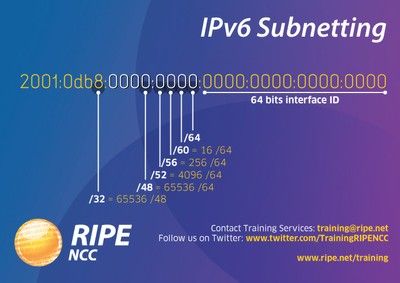
IPv6 subnetting
The design of the IPv6 address space differs significantly from IPv4. The primary reason for subnetting in IPv4 is to improve efficiency in the utilization of the relatively small address space available, particularly to enterprises. No such limitations exist in IPv6, as the large address space available, even to end-users, is not a limiting factor.
An RFC 4291 compliant subnet always uses IPv6 addresses with 64 bits for the host portion. It therefore has a /64 routing prefix (128?64 = the 64 most significant bits). Although it is technically possible to use smaller subnets, they are impractical for local area networks based on Ethernet technology, because 64 bits are required for stateless address auto configuration. The Internet Engineering Task Force recommends the use of /127 subnets for point-to-point links, which consist of only two hosts.
IPv6 does not implement special address formats for broadcast traffic or network numbers, and thus all addresses in a subnet are valid host addresses. The all-zeroes address is reserved as the Subnet-Router anycast address.
The recommended allocation for an IPv6 customer site was an address space with an 48-bit (/48) prefix. However, this recommendation was revised to encourage smaller blocks, for example using 56-bit prefixes. Another common allocation is a /64 prefix for a residential customer network.
Subnetting in IPv6 is based on the concepts of variable-length subnet masking (VLSM) and the Classless Inter-Domain Routing methodology. It is used to route traffic between the global allocation spaces and within customer networks between subnets and the Internet at large.